Regulator/Rectifier Help

toomuchstuff

XS400 Member
Messages
8
Reaction score
0
Points
1
Location
Peterborough, NH
Hi All,
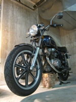
First post here. I have a 1981 XS400 Special, mostly stock (some re-wiring) which was running fine but boiling the battery off. I decided to upgrade the original reg/rect to a new Rick's combination unit for some improved technology. The original units (seperate regulator and rectifier) were charging at 14.9 volts when the revs were up, so that seemed to be a reasonable cause/effect relationship with the battery.
Put the new unit in and got no charging. I plugged the old regulator in while leaving the new rectifier connected and was back to charging. I assumed the new unit had a bad regulator section and returned it to Rick's (Who were great to work with) and they said it tested properly. Re-installed it and have the same result. The new rectifier seems to work fine but no charge at the battery. Plugged the old regulator in with the new rectifier and it charges properly, if a little high. I verified good connections to the regulator (both new and old) at the 3 pin connector.
I'm at a loss as to what to check next. Any suggestions gratefully accepted.
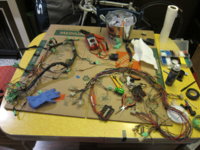
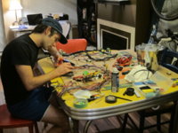
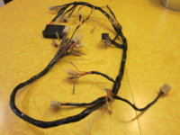
P.S. The re-wiring - I eliminated the original headlight relay and added switched XS650 handlebar controls with a basic relay. The original flasher was replaced with a basic 2 pin flasher with no auto-cancel. Fusebox was replaced with new style ATO fuses. Except for the overcharging, it was running well.
Thanks in advance for any help.
 
Looks like we are in a similar situation. See my post "Rick's reg/rec" a few below yours. Can you tell me how your Oem wire colors match to the Rick's wire color for the regulator?

Thanks in advance,

Clint
 
Looks like we are in a similar situation. See my post "Rick's reg/rec" a few below yours. Can you tell me how your Oem wire colors match to the Rick's wire color for the regulator?

Thanks in advance,

Clint
Hi Clint,

Unfortunately, I don't have my cheat sheet with me today. I'll check and get back to you tomorrow. When I sent my reg/rec into Rick's, they re-wired it with stock Yamaha colors to try and help, but no dice.
Gary
 
I don't have any reference material in front of me right now but earlier xs400s had regulators that switched the field coil path to ground whereas newer models (I think 80+) changed to switching the +12.

Electrical regulators don't necessarily work in both configurations. Could be an issue with Rick's.
The instructions might reflect only one configuration. If that's the case you will have to reconfigure the wiring to/from the field coil.

Not really relevant to your issue but maybe overcharging in general:
I started to make a thread yesterday about preventing overcharging of aftermarket batteries but didn't post it.
I was considering two options:
1. Stock rectifier with an aftermarket voltage regulator.
There are separate regulators available that will regulate to specific set voltages and even adjustable ones.
Don't have the link handy but there's a pretty affordable external regulator available for moto guzzis. Set it to 14.5V or whatever the battery is rated for and you'll never overcharge.
2. Use a 5 wire rectifier/regulator (not normally considered compatible with our bikes) in conjunction with a stock or aftermarket voltage regulator to control the field coil.
An appropriately selected regulator/rectifier will never allow a voltage high enough to overcharge through to the battery in the first place.
 
Toomuch- Thanks for the reply and for the help. I look forward to what your cheat sheet says.

Regards,

Clint

Hi Clint,
The cheat sheet says:
Rick's white wire to Yamaha green wire (field)
Rick's green wire to Yamaha black wire (ground)
Rick's black wire to Yamaha brown wire (+12v switched)
 
Toomuch- thanks for sharing, that is how Rick's told me to wire it when I called the other day. I hope to have mine running the the next week or so and will wire it like you have written to see what results I get.

Another question. When you swapped wires to make your harness match the regulator as stated from your cheat sheet, did you swap wires on the Ricks's plug or the Yamaha harness plug? I am just wondering if the way Rick's is telling us to wire it is incorrect since Rick's says your regulator tests fine and putting your old regulator back on the bike it charges?

I will try and call Rick's again tomorrow and ask what the purpose of each wire is on the regulator. If they will share that, maybe it will shed some light on your problem and how to wire mine.
 
Just double-checked Rick's website and it does not differentiate between -79 and 80+ model years despite them having different field coil configurations.

It probably means that it doesn't affect operations but when you call it might help to ask if their regulator needs to be between the field coil and +12V or between the field coil and ground.

I took a look at the parts listings and Yamaha calls for the same regulator for 1978 to 1981. I think it is the XS650 that changed from +12v to ground in 1979 or 1980. That has an alternator with brushes, so is different from the XS400. I know that the earlier 650s had 1 brush grounded and the later ones did not. I hope to have some time to poke at mine this weekend and run some further tests. I'll let you know if I find anything.
 
Toomuch and BBS, thanks for the replies. I called Rick's, again very nice, but the lady didn't know what the purpose of the 3 wires are nor did she have access to that info. The only thing she could tell me were how the Oem colors match to the Rick's plug.

I read this-

http://racetechelectric.com/ft-751-voltage-regulators.html


Seems like knowing this, should be able to use a multimeter and figure out how it should be wired. I hope you have some luck figuring it out this weekend.

Regards,

Clint H
 
I took a look at the parts listings and Yamaha calls for the same regulator for 1978 to 1981. I think it is the XS650 that changed from +12v to ground in 1979 or 1980. That has an alternator with brushes, so is different from the XS400. I know that the earlier 650s had 1 brush grounded and the later ones did not. I hope to have some time to poke at mine this weekend and run some further tests. I'll let you know if I find anything.
That only means that the Yamaha regulator works for both configurations.
Double-check the wiring diagrams and you'll see that it's different between earlier and later model years.

Brushes are just a means of transferring electricity to a rotary field coil.
Functionally brushes don't make any difference to the circuit, neither does whether the field coil connects to +12 or ground, but electronic components often have a polarity and the design may or may not take that into account.

Like I said, it probably doesn't make a difference but if someone designed an electronic regulator without knowing that both configurations are used they might not produce a configuration that works in both.

In all likelihood Rick's ought to work either way.
I just wanted to make mention of it since we've had two threads on Rick's regulators in one month but haven't previously had much feedback on Rick's units and which years of bike people have experience mounting them on.
 
I read this-
http://racetechelectric.com/ft-751-voltage-regulators.html
Seems like knowing this, should be able to use a multimeter and figure out how it should be wired. I hope you have some luck figuring it out this weekend.
Regards,
Clint H
I like your optimism. I've referred to that page before and it's good to get a general idea how our bikes function.

I will warn you that the actual regulators aren't simply an on or off switch.
The early mechanical regulators kept a resistor in series with the field coil for a low charge rate at all times and shorted it for full charge current to the field coil.
The newer regulators, OEM and Rick's, are electronic so you can't count on an open or closed contact or even a switching resistance being an indicator of anything concrete.
If we knew the electronic construction inside Rick's it might be possible to figure out what the leads would read with a multimeter.

The sure-fire diagnostic way of figuring it out would be to hook up a variable power supply, trying different combinations of + voltage and ground, and observing how the regulator's volt drop changes when the power supply voltage (simulated battery) changes below normal full-charge voltages.
There could be up to 2-3 (no field current, maintaining current, and full current) or infinitely variable charge rates depending on how complex/intelligent the charge circuit is.

Definitely give it a shot. I took resistance readings off the OEM regulator leads earlier and will post them when I get home.
Being electronic they don't necessarily indicate anything but if you get similar readings on Rick's you might be able to match up leads.

Edit: These are the resistance readings off the OEM electronic regulator.
I was thinking about it but I honestly have no idea how you'd go about testing the reg/rectifier combo unit in comparison to the stand alone regulator. The values will likely all be different but if you can figure out which leads to even test, similar ratios of readings to polarities might indicate something.
Best of luck though!
43.2 kOhm: Blk lead -> OEM Reg Brn, Red lead -> OEM Reg grn
31.7 kOhm: Blk lead -> OEM Reg Grn, Red lead -> OEM Reg brn

1.25 kOhm: black - brown, either lead polarity

44.6 kOhm: Blk lead -> OEM Blk, Red lead -> OEM Grn
30.5 kOhm: Blk lead -> OEM Grn, Red lead -> OEM Blk
 
Last edited:
I was battling with the same reg/rec from Rick's all weekend. I rebuilt my wiring harness from scratch, referencing the OEM wiring diagram, a simplified wiring diagram and Rick's cheat sheet. Turns out, the 'black' wire in the 5-plug connection actually goes to OEM brown, which is actually a black wire coming from the alternator. This is a switched hot wire I believe. The black wire from the 3-plug connection is also a switched hot. I know, confusing.

Here is the wiring diagram I made. Confirmed to start and run, and charge the battery at a nice 14.5v max.
xs400-wiring-harness-new.jpg
Toomuch and BBS, thanks for the replies. I called Rick's, again very nice, but the lady didn't know what the purpose of the 3 wires are nor did she have access to that info. The only thing she could tell me were how the Oem colors match to the Rick's plug.

I read this-

http://racetechelectric.com/ft-751-voltage-regulators.html


Seems like knowing this, should be able to use a multimeter and figure out how it should be wired. I hope you have some luck figuring it out this weekend.

Regards,

Clint H

I got a chance to run some tests this weekend and here's what I found:
My old regulator has +12v switched coming in on the brown wire. Black is the ground wire. Green is voltage out to the field coil. With the old regulator installed, when I turn the key ON, I get voltage out on the green wire and the field coil is energized (passes the slap test). When I start the engine with the Rick's rectifier plugged in and my old regulator installed, I get charging voltage at the battery. (Mine is a little high which is why I started this process in the first place.)
The Rick's unit does not act this way. When I turn the key ON, I have +12v on the (Yamaha brown, Rick's black) ground is (Yamaha black, Rick's green) and I get no voltage on the (Yamaha green, Rick's white). The field coil does not energize and I get no charging voltage with the engine running.
I spoke to Rick's again and was told my unit tested fine for them (They had taken it back and tested it). They graciously offered to take the unit back and that's the route I'm taking.
What I'm going to try now is a pre1980 XS650 reg/rec from Mike's XS. I looked at rafanomenon's wiring diagram but my color coding is different on the reg/rec side so it didn't make sense to me.
Best of luck.
 
Looks like I'm having the issues that you guys experienced on my 1979 Yamaha XS400. I bought a new Voltage R/R from Rick's and when I connect the voltage regulator portion it does not magnetize the field coil = no stator output. When I connect my old OEM regulator the system works? Has anyone found out how to make Rick's unit work?!? Or does it a dud design and just does not work with our bikes?
 
Looks like I'm having the issues that you guys experienced on my 1979 Yamaha XS400. I bought a new Voltage R/R from Rick's and when I connect the voltage regulator portion it does not magnetize the field coil = no stator output. When I connect my old OEM regulator the system works? Has anyone found out how to make Rick's unit work?!? Or does it a dud design and just does not work with our bikes?
Hi Motoman, After being too busy to even look at the bike all summer, I finally tracked the issue down and got it running last week. My XS400 is a 1981, and the stock setup had switched +12 volt feeding the field coil (brown wire feeding the field coil black wire at the 4 pin connector under the gas tank/seat junction) and the green wire from the field coil feeding the regulator (green to green wire) to have the regulator control the ground. The Rick's R/R (Part# 10-404) controls voltage out to the field coil. I had to disconnect the brown wire feeding the field coil at the 4 pin connector, and substitute a black wire running to a good ground. Working great ever since. A few words of caution: My Rick's R/R was re-wired to match the stock Yamaha wire colors, yours may have the standard Rick's wiring which I think was a different color on the Rick's harness. Use the wiring color guide that came from Rick's to verify. I just checked the Rick's website and see that the part number has changed since I purchased mine. If you have the 10-404, this advice applies, if you have the new listing 10-411, you will have to verify how it functions with respect to the field coil. What I did to test mine, was to disconnect the field coil connector (4 pin connector under the tank/seat junction) and turn the ignition key ON and measure for voltage between the green wire coming from the R/R and ground. If you have a voltage reading, then you need to change the voltage feed as I described. Best of luck with it.
 
I don't know about Ricks, but on my '79, the original regulator sent 12+ to the field coil when the ignition switch was on with the regulator turning the ground on and off to regulate charging. The newer regulator I used switched the 12+ for regulation, not the ground. I changed the wiring slightly to work with this configuration. I now have the brown 12+ wire going to the regulator with green going from the regulator to the field coil. However, I disconnected the brown wire (12+) from the field coil and connected a dedicated ground to the other pole of the field coil. So, now green is the regulated 12+ to the field coil and the black from the field coil goes the ground. the brown wire only goes to the regulator and is disconnected and capped before it goes to the field coil.

Like I said, I don't know about Ricks. This worked with the R292 regulator I used to replace my bad original, but if Rick's regulates current by switching the 12+ and your '79, like mine, originally ran 12+ to the field coil and switched the ground, it may work.
 
Hey guys, thanks for the responses. Sounds like you both are a touch more knowledgeable about motorcycle electronics than myself! Good work figuring that stuff out. That being said...still felt a little hesitant to make those changes for fear of making a mistake and repeating the catastrophic electrical issues that fried my old wiring harness to start with!!! You would not believe how fried my old harness was...so I'm going to show you
 

Attachments

  • IMG_9790.JPG
    IMG_9790.JPG
    134.3 KB · Views: 969
  • IMG_9793.JPG
    IMG_9793.JPG
    121.6 KB · Views: 720
  • IMG_9804.jpg
    IMG_9804.jpg
    158.3 KB · Views: 697
  • IMG_9805.jpg
    IMG_9805.jpg
    132 KB · Views: 499
More images...
I guess the problem had occurred with the previous owner and he had carefully wrapped all the fried areas with electrical tape. To his credit the bike ran ok for the first month I had it but then problems started to surface. I'm assuming that the burnt wires were grounding out...everywhere. A good word of caution when you see a lot of electrical tape on a wiring harness!!!
 

Attachments

  • IMG_9810.jpg
    IMG_9810.jpg
    117.7 KB · Views: 579
  • IMG_9875.JPG
    IMG_9875.JPG
    127.8 KB · Views: 619
  • IMG_9876.JPG
    IMG_9876.JPG
    125.9 KB · Views: 526
  • IMG_9903.JPG
    IMG_9903.JPG
    104.3 KB · Views: 565
  • IMG_9904.JPG
    IMG_9904.JPG
    142.8 KB · Views: 539
  • IMG_9905.JPG
    IMG_9905.JPG
    133.4 KB · Views: 638
  • IMG_9906.JPG
    IMG_9906.JPG
    124.6 KB · Views: 625
  • IMG_9907.JPG
    IMG_9907.JPG
    156 KB · Views: 615
  • IMG_9910.JPG
    IMG_9910.JPG
    132.5 KB · Views: 522
  • IMG_9919.jpg
    IMG_9919.jpg
    122.6 KB · Views: 627
  • IMG_9922.jpg
    IMG_9922.jpg
    136.3 KB · Views: 530
  • IMG_9922.jpg
    IMG_9922.jpg
    136.3 KB · Views: 585
  • IMG_9942.jpg
    IMG_9942.jpg
    109.1 KB · Views: 538
I ended up buying a good used wiring harness on ebay and checked every single wire and connection for resistance. I then replaced all of the fried wires to the various components on the bike. I also replaced the R/R...believing that failure of the original Voltage regulator may have been one component that caused this massive melt down. It was a bit of a tedious undertaking. I think next round, if I ever have to replace a wiring harness, I will make my own slimmed down harness. I just didn't feel confident with motorcycle electrics quite yet. Unbelievable how much I learned in that process!! Diving in and just doing it is the only way to learn. It's gotta be hands on!!
 

Attachments

  • IMG_9887.JPG
    IMG_9887.JPG
    237.2 KB · Views: 541
  • IMG_9892.JPG
    IMG_9892.JPG
    196.8 KB · Views: 521
  • IMG_9900.JPG
    IMG_9900.JPG
    172.7 KB · Views: 552
  • IMG_5382_2.jpg
    IMG_5382_2.jpg
    209.8 KB · Views: 641
Back
Top