I bought a new electronic speedo/tach combo which happened to have gear indicator inputs so I figured I may as well make use of them. Making a indicator switch has been done before but not well documented so here it goes.

Start this project by removing the chain guard from the side of the machine (this happens to be an 82 DOHC Maxim). From here you can remove the neutral switch. This is also a good time to clean this area from the road shmoo that accumulates from chain lube and dirt.


Life of the Gear indicator switch starts as a lowly neutral switch, however this is about to change.

A little bit of time on the lathe and the switch is all bored out. Seeing as though I took these pictures a while ago I can't remember the exact dimension but it is the same size as the stamped metal circle that holds the brass contact. We will get to that later.

Next it is important to change the chuck in the lathe because the correct one is always sitting on the bench.
Then change it back because you completely over thought this step and actually want the chuck that is now on the bench.

More lathe time means that you now have a piece of non-conductive material (this happens to be acrylic) that is a snug fit in the bore that was made earlier.

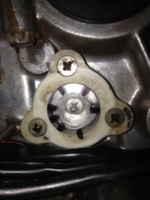
This screw retains this "contactor plate" and brass contact that come out of the bike from the neutral switch assembly. As you change gears the plate rotated about the axis of the screw which in turn moves the contact into different locations. This fact is what allows us to make this part.

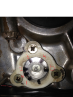
The markings on the acrylic are made by putting the part back on the bike and using the transparent properties of the acrylic to mark where the contactor is at each gear position(the brass contact can be seen behind the right most mark in the picture above).
NOTE: The mark that is on both the acrylic and base material is just a reference for when the part is taken apart and reassembled.

Now because the bore is only slightly larger than the "contactor plate", it can be used to mark the bolt circle of the holes to be drilled. This and the radial marks made earlier will be the actual locations.


Now it is just a matter of drilling and tapping. The use of WD-40 and a bottoming tap make the process of tapping acrylic much more enjoyable.


Another tooling change and some brass 8-32 screws can be turned to studs and parted to length.

Now just thread in the newly made studs with some superglue to help seal and bond them(locktight may not fully cure as it needs a metallic base on both sides of the fastener. here we have acrylic i.e. not metallic).
Make sure to sand the screws flush on the inboard side of the part allow smooth operation.

Because brass screws were used, you can now solder on the wires to be connected to the tach. I used some leftover wire from an ls swap into a 1977 squarebody. Either way the use of temperature rated wire is advised.
 Now some epoxy(In this case everyone favorite JB weld) is used to seal and attach the acrylic to the base part. Now some wire loom makes the project a little cleaner.
Some assembly and you're done.
It is worth mentioning that this type of modification will switch a ground signal to the wire corresponding to the current gear. This may or may not be what your specific application requires.
Start this project by removing the chain guard from the side of the machine (this happens to be an 82 DOHC Maxim). From here you can remove the neutral switch. This is also a good time to clean this area from the road shmoo that accumulates from chain lube and dirt.
Life of the Gear indicator switch starts as a lowly neutral switch, however this is about to change.
A little bit of time on the lathe and the switch is all bored out. Seeing as though I took these pictures a while ago I can't remember the exact dimension but it is the same size as the stamped metal circle that holds the brass contact. We will get to that later.
Next it is important to change the chuck in the lathe because the correct one is always sitting on the bench.
Then change it back because you completely over thought this step and actually want the chuck that is now on the bench.
More lathe time means that you now have a piece of non-conductive material (this happens to be acrylic) that is a snug fit in the bore that was made earlier.
This screw retains this "contactor plate" and brass contact that come out of the bike from the neutral switch assembly. As you change gears the plate rotated about the axis of the screw which in turn moves the contact into different locations. This fact is what allows us to make this part.
The markings on the acrylic are made by putting the part back on the bike and using the transparent properties of the acrylic to mark where the contactor is at each gear position(the brass contact can be seen behind the right most mark in the picture above).
NOTE: The mark that is on both the acrylic and base material is just a reference for when the part is taken apart and reassembled.
Now because the bore is only slightly larger than the "contactor plate", it can be used to mark the bolt circle of the holes to be drilled. This and the radial marks made earlier will be the actual locations.
Now it is just a matter of drilling and tapping. The use of WD-40 and a bottoming tap make the process of tapping acrylic much more enjoyable.
Another tooling change and some brass 8-32 screws can be turned to studs and parted to length.
Now just thread in the newly made studs with some superglue to help seal and bond them(locktight may not fully cure as it needs a metallic base on both sides of the fastener. here we have acrylic i.e. not metallic).
Make sure to sand the screws flush on the inboard side of the part allow smooth operation.
Because brass screws were used, you can now solder on the wires to be connected to the tach. I used some leftover wire from an ls swap into a 1977 squarebody. Either way the use of temperature rated wire is advised.
Some assembly and you're done.
It is worth mentioning that this type of modification will switch a ground signal to the wire corresponding to the current gear. This may or may not be what your specific application requires.