How to: flasher relay for LED turn signal

There are some photos showing the relay plug location in the first post of this thtead.
It's the circled connector in the first photo.
 
This is a great and easy fix. Thanks for putting it up. It saved me a huge headache. I just spliced the green/yellow back to the black/ground wire on the flasher cancelling plug. It tucks up very nicely under the seat.
 
Hi I just tried to follow these steps and I did not have any success. It’s worse than before. I installed the new relay and grounded the yellow/green wire, but now the blinkers are very dim and still stay solid. The stock relay is brighter. Very confused, anyone have any ideas?
 
I am suspicious of the turn signal light cross over. (idk if you have a newer bike than 81, that would not be the issue then. see post 16. LED's turn out to be super sensitive to any electical pulse/current. and the turn signal will bleed power from left to right. which a diode kit will block that small power transfer.
( I am just guessing) easy to to check, pull out the flasher bulb. (I think, its been 3 years since I did this update)
http://www.xs400.com/threads/how-to-flasher-relay-for-led-turn-signal.10601/#post-150085
 
Hey guys I have an 1981 400sx and I did this relay mod. I have a universal led bar. It works but I am having the hazard issue. I’m confused where the diodes go exactly. Can anyone clarify?
 
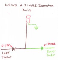
I edited this post because I made up diagram showing the diodes and how they wire in.
Find the wires going to the turn signal indicator. One lead will be dark green the other chocolate. These leads come from the left and right sides. Cut them off about half way between the bulb and connector.
If you are using the stock bulb polarity won't matter.
A diode is a one way valve for electricity. On the diodes, in my diagram they are shown as an arrowhead with a line across the point. This arrow head points to the direction of flow. In real life they have black body with a grey line around it near one end. This shows you which way the power flows, the banded end is the output end.
Hook the to outputs together and hook these to one wire to the indicator bulb. Ground the other wire from the indicator bulb.
Hook the other ends of the diodes to the left and right turn signal wire.
Now if you use a LED indicator bulb then you might have a polarity issue. Some LED's work only if power flows the right way. Some don't. Find the positive lead of the LED. Hook this lead to where the outputs from the two diodes come together.
Leo
 

Attachments

  • Diodes for turn signals 001.jpg
    Diodes for turn signals 001.jpg
    72.2 KB · Views: 411
Last edited:
Thanks Leo. Turn signals are working perfectly! I was just confused earlier by the term “indicator” as a turn signal light is often referred to as a turn indicator. I also discovered that simply removing the bulb from the dash light corrects the hazard problem... (lame solution) I wired in the diodes because having the dash light working is very nice and helpful. Thanks for the info everyone!
 
Back
Top