1982 seca xs400 build (New thread)

So I found this little bit of useful information. So according to this the black/white wire coming from the ignition can just be capped right?

Also according to this info the safety relay has a diode that acts as a resistor. I am going to get rid of the relay, so do I need to put a diode in its place or do I just connect the wire? If I need a diode what kind do I use?

One of the most frustrating problems you can run into is a bike that refuses to crank over, or will crank over but won't ever fire. Assuming it's not an engine (fuel or mechanical condition) issue, then it may be caused by your electrical system; more specifically, by the rather unique system of inter-related devices that Yamaha collectively refers to as their "safety switch system". Consisting of assorted switches, relays and their wiring, you may have to do some heavy-duty electrical sleuthing in order to determine where the problem resides.

Curiously, Yamaha used the same general style of "cube" relays in a variety of different positions for the safety system, and although they all look virtually identical to each other, they in fact all perform differently. But since they are all interchangeable......a headlight relay, for instance, will happily plug into the sidestand relay wiring harness connector shell....so the first troubleshooting step is to make sure that each relay is correct and in its correct position.

For instance, the sidestand relay is a normally closed relay while the others relays are normally open. The head light relay and the ignition cut off relay (also called the neutral safety relay) both contain diodes, which means that they are controlling voltage coming from two different sources. Although they are both normally open and both contain diodes, they are still vastly different in their coil resistance ratings and are thus not interchangeable.

Since an incorrectly positioned relay will typically not work, or will work "incorrectly" when placed at the wrong position in the harness, determining whether relays are properly positioned, and of the proper "type", can save you some more painful types of troubleshooting!
 
Yep you just need to cap the black/white wire. The black/white is supposed to kill the ignition when grounded. When the side stand is engaged the black/white wire is grounded, so if you dont want to run a side stand relay simply eliminate the black/white wire or if you dont want to fiddle with those connections cap it. Once the black/white wire is capped just cut the relay out. The red/white wire also needs to be capped because it is the power source of the relay, and you don't want it exposed.

Hope this helps for any of those that want to remove the relay.

Still not sure what to do about the clutch relay, do I need a diode? or can I just connect red/white red/white. Thanks guys
 
SHIIITTT back to school this week looks like the bike is getting put on a hiatus.
 
Sorry man - your questions are coming faster than we can answer them!

I haven't done any relay removals. My recommendation would be to do them last, after you know the rest of your wiring works properly. I'm not a big fan of making a whole bunch of changes and THEN testing, as you'll never know which change is screwing you up.

The next time I have my battery hooked up, I'll check the headlight. In all honesty, it probably won't be until next week given the week I have ahead of me...
 
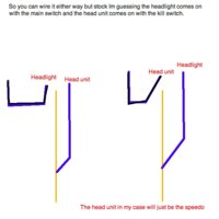
So I was some what wrong and right about the head light. It will come on no matter the position of the kill switch, but the kill switch does work double duty (checked it with a volteometer or whatever). Ill explain.

The ignition switch turns on the speedo and head assembly. On my harness there is a blue wire that is connected to the ignition wire that comes from the fuse box. so when the key is turned on the light will come on. It could be ran so the ignition switch turns on the light, but after looking about it I dont think thats how it would be stock. oops
 
AHHHH O made another mistake. The blue wire comes off of the head fuse not not ignition fuse.
 
Kill switch wires.jpg

So the yellow/red wire comes from the head fuse and the blue/black wire comes from the kill switch.:thumbsup:
 
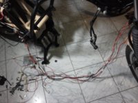
So I am almost done with electrical. I got the harness together. Now I just need to add connections. Also bought one of those cheap plugs for the tach hole and it works perfect (not very pretty thought).


Wiring start.jpg

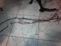
Progress on the wiring

Wiring harness one.jpg

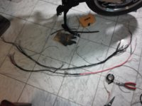
And the final result

Harness finished.jpg

Here is a pic of the little plug in the tach hole.

Tach plug.jpg
 
I have been puzzling that one for a while. I hate to say it, but I may weld a small tab onto the frame so it has something to hang from. That's probably the easiest solution...

UUUUgh it all painted and shiny though. I guess I will have to rig something up.

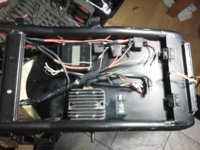
Here are all the wires in the rear housing

rear wiring.jpg
 
Hey....
You're polished engine looks the nuts!!!....I am using an XS400 DOHC in my chop build(see my pics/album),and although the cases and fins etc. are in in good condition,the clear laquer has all bubbled!
Was yours like this before you started?
I was gonna get it soda blasted,but the quote I had was over £100!!
Did you have to rub yours down,and remove bad laquer etc?,
and if so,how did you do it?
cheers
Roger :)

When I started there was some nasty flaky shit on my cover, but i thought it was just salt corrosion(it cold have very well been lacquer). It is a multiple step process. Start by sanding the covers down with 320 grit auto sand paper. Then 600 grit then 1500 grit then 2000 grit, and finally buff it out with polish. Polish alone wont give you nearly the luster as the process I just explained.

Oh ya and a couple of tips when you do it. I recommend waring some latex gloves, and wet sanding. Wet sanding will make your sand paper last a lot longer.
 
Ok guys my electrical is pretty much done. A few connections here and there. I am looking for some information on my ground wires. I have left a couple of feet for all of my ground wires but Im not sure where to connect them. I see the battery grounds to the engine, so I should be able to ground anywhere on the frame right? I would imagine I need to sand the frame where I connect the grounds, but could I also just pinch the wires with washers eliminating clearing the frame of paint?

Any suggestions would be great.
 
Ya I understand that the grounds can be connected, but I was just double checking on how to connect them to the frame.
 
I was told that the rectifier and regulator need air. That's why I didn't put them under my seat like that. Anyone have an idea if Ksqrly's set up here is sufficient enough?

I'm in a pickle with my wiring. I have a short somewhere and keep blowing fuses. I'm considering just rewiring the whole thing. Ksqrly.... do you think it's worth it? If you had to do it again would you just make smaller changes to the original harness or do it from scratch?
Also, if you bought new wires and all the connectors, where in SLC did you get them?

I should have plenty of air flow under the seat where it is. It is more exposed than the stock positioning so Im not worried. As far as building the harness goes I would just build one from scratch, and use your old harness as a reference. The only problem I ran into with that was finding all of the different colored wires sold by the foot. It is possible to buy rolls of the stuff but I couldnt find every color I needed by the foot.

As far as connections go. I used mostly bullet connections. I wasnt sure on this idea, but I checked in with drewp and thats what he did, and he says it works great. If you want to go big and get multi pin connectors there is a great little electric shop called RA-ELCO, and I think it is on about 2500 S. and State.

One quick comment. If you go with bullet connectors get the ones that are uninsulated. They crimp on much better
 
Ksqrly,
I believe you already asked this but I can't remember where. You can remove the Flasher Canceling unit, kickstand switch, Neutral switch assembly and oil pressure switch assembly altogether correct?

Currently, for those things I just have the wires cut and then soldered back to themselves to complete the switch.
If you remove them altogether during the rewire does it create problems?
 
Back
Top