82 Maxim DOHC 400 electronics retrofit

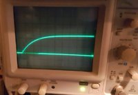
I cant believe how long this has taken me... but I got a spark plug setup via arduino! This was all done in my dorm room at college, so the connections are sketchy at best. Acutally, Im not even going to send in a picture it was so sketchy haha. I got a spark though! Used an old computer charger, rated for 12v at 2.09 amps. The spark was incredibly weak - not NEAR enough to sustain an engine, but it was there nonetheless! I believe it was very weak because of the voltage drop in my sketchy connections, and the fact that I only had about 2 amps to play with.

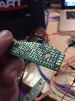
I will include a picture of the sensor mounts. I think I finally developed the best possible way to mount them. Not unlike a Pamco setup. Which begs a question - why didnt I just go with that from the get go? Well for starters, it isnt made for a DOHC xs400. Secondly, I love learning about this kind stuff. Thirdly, theyre a little expensive (in reality, the time Ive spent on this far outweighs the $150 or so for the Pamco - if i could buy one of those, i probably would) but, I dont have a ton of cash around. Im about $15 into this project so far, and dont plan to spend more than another $15 on parts

I think its coming alone well though! So far I have:

-hall sensors/mounts
-coil firing via Arduino-sensed input from hall sensors
-primitive code written

Really, my next step is to get this system I created in my dorm onto a garage bench and less sketchy, mount the coils/arduino and test! Very excited to report the results!!
 

Attachments

  • sensor_mount.JPG
    sensor_mount.JPG
    128 KB · Views: 429
Cool. What are you using to drive the coil? A MOSFET or IGBT?

I gave up on the parts ordered from overseas and ordered from digikey. Should have enough parts to fire plugs this week.
Getting my wife to make some test rig brackets at work. Angle iron with mounting holes for coils and tapped holes for spark plugs.
 
Currently a MOSFET, but I have an IGBT on order. Specifically, a Fairchild FGP3440G2_F085. Made for running coils, so it says. I plan to rig it with a MOSFET, and if that works, swap in the Fairchild for actual usage.
 
I splurged on three different types of IGBT.
IRGB14C40LPBF-ND (same as Pamco and other DIY ignitions)
FGD3245G2_F085CT-ND (cheaper, 1.25 Vce)
FGP3040G2_F085-ND (similar to above but surface mount)
Since our bikes aren't too demanding I wasn't sure how to pick the "best" one for the job. Seems like just about any common IGBT would work.
Bought the IRGB14C40 because it's been proven to work but it is relatively expensive and the Vce is pretty high at 1.75V.
Vce seemed like a good parameter to help choose IGBTs because lower values will mean more voltage at the ignition coils.
Yours has the lowest Vce drop of any available so probably a good choice.
1.2V vs 1.75V on the IRGB14C40.
Only half a volt but that's around a 5% improvement.
 
Yep, I was watching the Vce value, along with the threshold voltage on the gate. Thats what "turns on" or "flips the switch" of the mosfet. Just make sure your threshold voltage is under 5v, because that is logic-level of arduino. You could always use a boost converter or voltage step up device of some sort I suppose. The IRGB14C40 is a "logic-level" voltage per the datasheet i looked up, so that should work great!

Same though, I dont really know the correct driver to use, or even MOSFET vs IGBT. Im sure theres one that would be optimal, but Im just looking for a reliable, working system.

EDIT FOR FUTURE READERS: wait, I see now how Vce is basically the same as the threshold voltage. MOSFETs have 3 pins, gate, drain, and source. IGBT (or transistors) are collector, base, and emitter. Similar, but not the same.
 
Im laying out a Fritzing diagram of my circut and stuff. Do you think the IGBT coil drivers are going to get hot enough to need heatsinking?
 
Im laying out a Fritzing diagram of my circut and stuff. Do you think the IGBT coil drivers are going to get hot enough to need heatsinking?
Yes. Take a look at the stock TCI module as an example. Sure, it is 35+ year old tech, but many have survived and are still functional. And the transistors were mounted on heatsinks.

Considering the effort you are investing, I'd suggest designing with a "last forever" goal. Good thermal management, reverse polarity and over voltage protection, EMI shielding. EMP mitigation...
 
Considering the effort you are investing, I'd suggest designing with a "last forever" goal. Good thermal management, reverse polarity and over voltage protection, EMI shielding. EMP mitigation...

Ill wrap it in tinfoil if I have to.

In all seriousness, I defienitly agree with that sentiment. Thats why I asked about the heat sinking. My Fritzing diagram already has a voltage regulator wired in, however I really like the idea of reverse polarity protection. Seems very possibly with a couple strategically placed diodes.

Actually, Im having a rather hard time imagining a design for a small box (similar to a TCI box) that dissipates heat appropriatly. If anyone has suggestions, I'd love input and a drawing!
 
Last edited:
Pete used an aluminum box for his e-advance unit for 3ohm coil bikes. Bolted his IGBTs to the inside of the box.
Probably necessary for your 2.5ohm coils, though I think your IGBTs can handle more total current.

Which voltage regulator are you using? The automotive ones are supposed to be pretty robust, but some diodes for protection will be good, especially freewheeling diodes across the coil terminals.
I have a handful of LM2940s, or the LM2931 is adjustable as per: http://arduino.stackexchange.com/questions/12333/motorcycle-battery-powering-arduino-uno/12338
 
I currently have a AN78M10, but thats just what I had around. Think its 10v. Seems like the datasheet on the LM2931 is promising. Designed for automotive applications, and I think it said it had reverse polarity protection built it.

The problem with bolting the IGBT directly to the heatsink, the mounting tab on alot of TO-220 packages doubles as a conductive point of the Drain (on an IGBT, it would be Collector pin, I think). Just checked the datasheet for the IGBT i got (FGP3440G2_F085) and it didnt specify that in the pinout, so I guess I can assume that the mounting tab isnt conductive?
 
Yeah, that's usually the case when the tab is metal. Looks like the flange is the collector on the TO-252 version. I doubt it'd be different on the TO-220.

There are thermally conductive insulator sheets for TO-220 devices to enable bolting them to grounded heat sinks.
 
Playing with some code, and so far this has been working well:

boolean val;
int led = 2;
int var;
int pickup = A0;

void setup() {
pinMode(pickup, INPUT);
pinMode(led, OUTPUT);
Serial.begin(9600);
}

void loop() {
Serial.println(digitalRead(pickup));
var = digitalRead(pickup);
if (var == LOW) {
if (digitalRead(led) == LOW && val == false){
//delay(1000); this is the advance in ms
digitalWrite(led, HIGH);
delay(15); //this is the dwell time
digitalWrite(led, LOW);
}
val = true;
}
else (val = false);
}

This basically just makes it so that when it senses the input from the hall sensor, it doesnt keep grounding the coil while it senses the hall sensor being triggered. This way, the dwell is independent of the speed at which the magnet passes the sensor.

I got it hooked up to my motorcycle this weekend! I had it all rigged up and actually ready to test but I dropped a small piece of wood into the cylinder. Thats right folks, Im that clumsy. Ended up not being able to get it out, and I didnt want to crank the engine with that little chunk of wood in there. So Ill be back at it agian this coming weekend I hope.

Also, the spark didnt seem to want to spark 100% consistently. I'd say maybe 70% or 80%. Im not sure what was up with that. When I set the delay with the dwell to anything under than 6ms it wouldnt spark at all. If my code is written with correctly, that means that it need at least 6ms of dwell to spark... but that cant be right. Any insight?
 
The first delay is commented out, but 1000ms advance?
15ms dwell?
No interrupts yet?
Using a rising edge interrupt should accomplish the same thing you're trying to do.

Got my test rig working. Here's the current-rise trace for the SOHC 3ohm coils.
20170221_220302_resized.jpg

Each horizontal division is 1ms. Based on the megasquirt dwell info I'd say 3.5ms should be more than enough for the 3 ohm coils.
Gives bright blue/purple sparks all the way down to 1.5ms where they start to look faint.
I'd expect the DOHC 2.5ohm coils would need less dwell time with their lower resistance, not more.
 

Attachments

  • 20170221_220302_resized.jpg
    20170221_220302_resized.jpg
    111.4 KB · Views: 410
Might be something to with the wiring. Is there any resistance inn the primary circuit of the coils?
Any chance the IGBT collector and drain are swapped? It might still conduct poorly the wrong way around.
 
haha yeah, 1000ms dwell just so I could see it with my eye. I am going to check the swapping of the collector and drain pin. Do you have a wiring diagram of your setup? Mine wouldn't spark when set below 5ms... no idea why. I'd love to see some more pics of your setup!

Did your code use interrupts? I obviously didnt, and now im wondering if that is why mine wouldnt spark below 5ms.
 
I haven't wired up any trigger sensors or coded anything beyond my first untested version above for triggering.
Got past a big hurdle at work so might find time to get something going. Haven't figured out how to test the optical triggering or how to mount the optical disk to the camshaft of the motor.
Been meaning to put this all into Fritzing or Eagle but haven't gotten around to it. In the mean-time:
20170224_212754 (Medium).jpg

The two TO220s to the left are the IGBTs. The one closer to the arduino is a 7805 voltage regulator.
The positive rail at the top of the breadboard is the battery +12V. The bottom rail is the 5V from the regulator that feeds the arduino.
The yellow and orange wires from the arduino digital pins go to the IGBT gates via a few resistors. (Currently 150ohm but there's probably a better value)
The IGBT at the top has a pulldown resistor, no pulldown on the bottom IGBT. Some info suggested that pulling the gate to ground will help the IGBT shut off faster but it doesn't seem to make a difference. The arduino digital pins must ground well enough internally.
One ignition coil lead goes to the +12V rail, the other goes to the IGBT drain.
IGBT source goes to a 0.01ohm current sensing resistor, then to ground.
 
Just hammered this out.
It's incomplete. Don't knof it it'd actually work.
The var variable needs to be declared volatile. Math is probably wrong. Using delays with interrupts might break everything, except the triggering shouldn't ever overlap with a motor spinning so might actually work....
Code:
int led = 2;
int var = 0;
int pickup = A0;

void setup() {
  pinMode(led, OUTPUT);
  pinMode(pickup, INPUT_PULLUP);
  attachInterrupt(digitalPinToInterrupt(pickup), PICKUP, RISING);
  Serial.begin(9600);
}

void loop() {
  Serial.println(digitalRead(pickup));
  if (var == 1) {
    delayMicroseconds(48611); //10 degree advance at 1200 rpm (my math is probably wrong)
    digitalWrite(led, HIGH);
    delayMicroseconds(3500); //3.5ms dwell
    digitalWrite(led, LOW);
    var = 0;
  }
}
else (val = false);
}
void PICKUP() {
  var = 1;
}
 
Well, this weekend was the first test on an actual engine. I did the test where you take the plug out and hold it agianst the engine to ground it, and it sparked great during engine cranking! Big, blue sparks. I sprayed a small jet of starting fluid in the spark plug hole and put the plug back it and tried cranking it. Nothing. However, I did get a big backfire out the exhaust (after a few seconds of cranking)! So theres the first explosion this motorcycle has had in a LONG time!! That means its probably quite rich - thats to be expected, becasue spraying starter fluid is pretty aggressive. So i tried to dribble a little bit of gasoline in there - about 1-2oz. Nothing. Not even a backfire. Starting spray agian, same backfire. No carbs on it.

Any advice? Im 99.9999999% i have spark (im 100% sure, unless it stops sparking when in the cylinder) and that was the main thing vexing me since summer, so that a big step forward!
 
Any code changes since the above snippet?
I was wondering how you're timing and firing the second cylinder?
I imagine DOHC bikes are still a 180° crank?

A timing light will help a lot too.
 
Back
Top