Adding a little Raspberry Pi to my 82'Heritage Special.

I was going to offer my raspberri pi but discovered that it's an older "B" model. Fewer USB ports and higher power consumption.
Apparently the biggest power waste on the A model is the voltage regulator: http://www.raspberrypi.org/forums/viewtopic.php?f=29&t=32955
If it's the same situation on the B+ you might be able to add a more efficient switching power supply.

I've mocked up my arduino-powered flasher/canceller on a breadboard. Just waiting on a few parts to arrive before testing the functions.
 
I've mocked up my arduino-powered flasher/canceller on a breadboard. Just waiting on a few parts to arrive before testing the functions.

I saw that on another thread. That looks great. I did not invest in a breadboard, mainly because once the programming is finished, wouldn't have much use for it, but it would make things easier.:shrug:

I sqeeled like a giddy schoolgirl last night when my my bluetooth dongle and my 8-relay GPIO board came in. I hooked up the relays and found a few minor issues. It turns out that some of the GPIO ports are HIGH and some are LOW so some of the relays came on instantly and one of them was having some power issues. Next I told python to set all the GPIO to LOW and they all turned on (which I though was backwards):confused:. Set them to HIGH and they all shut off. played with them for a while and all the relays seem to work just fine. This issue will resolve when I add the program to the boot sequence later. I followed this youtube video to set up the relays:
. The comment section has a link to example code to get the relays working.

Here is the relay board I am using: http://www.amazon.com/gp/product/B00R77PN1A/ref=oh_aui_detailpage_o00_s01?ie=UTF8&psc=1
It is rated to 30V 10A so that should run most everything except the main ignition wire which will be powered through a universal car relay powered by the relay board (I'm using a relay to power a relay.lol)

Had trouble pairing my bluetoooth. I installed Bluez and Blueman and the GUI ran after install. However, after reboot I can't get the GUI to come up again. My phone sees my pi but the pin doesn't work. I think the pi needs to be able to see phone as well for this to work. I was hoping to find a Class 3 dongle (1 meter range) but those are apparently non existent so I got a class 2 (30 meter) but apparently BT can estimate distance from the device so with a little extra programming, I can set it to throw the relay when the phone gets within a certain distance as opposed to just when the phone pairs to it.

Now that I have the B+ model, I think I am going to add a touch screen monitor, and use it as a speedometer, tachometer, and navigation with a GPS Dongle. I'm still not sure whether a hall sensor or a reed switch is the better option. It will probably come down to price. I'm open to suggestions on that one.

Since I am using the B+ now instead of the A+, I will also eventually spend some BIG $$$ and get the largest amp-hour lithium battery I can find at some point but not until I get a feel of just how much power drain I'm going to get from the pi.
 
if you're still having issues with writing "HIGH" and turning everything off, and writing "LOW" and everything turning on, your uc is using pullup resistors. If it doesnt bother you, leave it this way. The reason it works like that is because the board is capable of sinking more current than it can source. Using pullup resistors allows you to write LOW to turn things on so that your GPIO pins are just sinking instead of sourcing. If you dont like thinking in that logic, most uc's datasheets cover how to disable them.

Cool project all in all, keeping an eye on your progress :thumbsup:
 
So I guess then I need to set them to be pulldown resistors instead. I thought pullup and pulldown were only for inputs. I didn't realize it was that way for outputs as well.
 
Well im not very familiar with your hardware or compiler, but its an industry standard for the most part to utilize pullups on your output pins. It's just funky because your output is actually sinking current so everything polarity-sensitive would need to be reversed and wired hot from a 3-7V rail most likely regulated off of whatever you are using to power your board. If you aren't using anything that draws much, disabling pullups would be fine, they're just used to keep from over drawing on the gpio pins of your uc
 
but hey, i might be full of sh*t in this case. All of my experiences in education and industry with ucs leads me to believe that the pullups are giving you your opposite logic but i have not done much with the consumer Pi stuff so make whatever you want of it :shrug:
 
Hope you don't mind me posting this, I was thinking about doing something similar. I am a very beginner/novice when it comes to programming and electronics. Found a similar set up someone was doing called scootputer. Here is his code he used. To find out more about scooterputer, you will need to good it and he explains what he is doing and using.
 

Attachments

  • Scooterputer_Arduino.pdf
    66 KB · Views: 397
  • Scooterputer_TouchShield.pdf
    57 KB · Views: 352
Thanks Norman. That looks like some pretty good information. Unfortunately for me, I don't think I could do much with it as it's not python programming and I too am a complete n00b. Since it's arduino it's probably C++ but I have no idea what the syntax is. However, I bet BS360 would probably be interested in this code.
 
That's some pretty nifty code. Good to have an example of those functions. I might still try to add a screen & interface.

The breadboard does make it easier to get things working and experiment. I think it was $1 direct from China, like most of the electronic components I've bought.
The most recent batch of components arrived yesterday. Everything works nicely with the correct resistor values installed.
Now to poke away at the code, make it do what it's supposed to do.

Might start assembling the auto-canceller connector and prototype PCB.
 
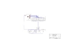
Started on the new Wiring Schematic today. Basically Just put in the Charging system and the Pi w/ relay board. I still need to put in the ignition, lights, ans switches. I just wanted to show off the progress so far. You will notice I'm running 2 main ignition wires. this is because, the relays are only rated to 10A. Since the main ignition is 20A, I had to split it into 2 circuits. Let me kow what you think or if you think I should split the circuits any differently as I might have two big current draws on 1 circuit. That would be bad.

BTW, I'm using TinyCAD.
 

Attachments

  • My Schematic with Pi.jpg
    My Schematic with Pi.jpg
    64.1 KB · Views: 280
Last edited:
If the main ignition actually draws 20A, you'd still be running your 2 10A relays at their maximum, which would work, but extended maximum exposure is usually not recommended. Are the relays that you're using with your pi easily exchangeable or are you pretty limited?
 
They are limited as far as I know. 10A relay boards are the standard. That said, 10A is the design limit but probably not what will be going through the relay given normal operation. I will double check all the currents when I install it to make sure I am below that. I very well should be considering I'm probably going to convert the lights to LED as well.
 
TinyCad is pretty good. Been doing mine with it.
Might try Eagle sometime.

I noticed your Pi doesn't have a connection to ground.
 

Attachments

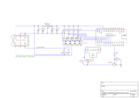
  • FlasherAutoCancel 0.0.3.png
    FlasherAutoCancel 0.0.3.png
    87.5 KB · Views: 302
You can't really use a transformer there at all. Transformers work on alternating current. The 12V supply doesn't alternate and won't transform with a transformer at all.

Another voltage regulator would work, or a buck converter. Voltage regulators waste a lot of energy. The 7V difference between 12V and 5V is essentially dumped as heat.
Buck converters are much more efficient, using less energy overall.

The Pi itself needs a +5V connection and a ground connection. With a voltage regulator the ground could still be to the frame but with a buck converter the +5 and gnd would both go from the Pi to the converter.
 
There are plenty of cheaper ones on Ebay of course but I just found this little buck converter: http://www.adafruit.com/product/1385
They also carry these guys: http://www.adafruit.com/products/1065
The price is steep but if you do need to really minimize power consumption for the wireless ignition one of them might be a good option.

They are a more reliable company than all the china-direct sellers on Ebay.

Also found this one: http://www.dx.com/p/dc-6-5-24v-to-5v-mini-buck-converter-power-supply-module-for-diy-156969#.VLcqSdzF_g0
Can't find much info online about it though. I'd question the quality but the compact size is nice.
 
I apologize, I think I misspoke on the whole transformer thing. Here is what I bought from Amazon to power the pi from my battery:http://www.amazon.com/gp/product/B00KKI4C1U/ref=oh_aui_detailpage_o00_s00?ie=UTF8&psc=1

A little pretext to my electrical knowledge. I had to take Basic Elec Engineering for a semester about 5 years ago and I got a C . Partly because I didn't care at the time (I am civil) and partly because I had no idea WTF was going on so I hope you understand why I thought o myself "Oh it changes voltages, it's obviously a transformer." To be honest, that power supply is made of magical fairy dust as far as I know. Although now that I have more of a desire to learn this stuff, it's slowly starting to make sense. Unfortunately, I'm sure that's not the last n00b statement I will make before this is over:shrug:.

So back to the question at hand, will the pi be grounded through the power supply?
 
Yep, that supply provides the +5 and the gnd, especially if it will plug directly into the Pi with the USB connector.

That probably is about as efficient as a Pi's power supply can be.
In a way it is kind of a high-tech transformer.

I went with a smaller voltage regulator for my arduino. It will only be on while the bike is on so the consumption wasn't as much of an issue.


My arduino's most basic code is working. The flasher flashes and the auto-canceller cancels after 500ft.
Might add a time limit too. Something like 45 seconds but only if the bike is moving. That'll keep it flashing while at stop lights.

There are still two digital inputs completely unused right now. Might try to figure out an RPM monitor.
 
Back
Top