EFI Kit DOHC

Blake_Volpex

XS400 Member
Messages
10
Reaction score
13
Points
3
Location
Perth Ontario
I started working on fuel injecting a DOHC XS400
Based around a custom Speeduino based ECU.
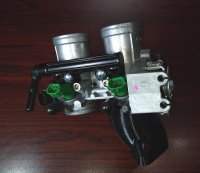
Using a throttle body from an EX300 as they are cheap, plentiful, and the injectors are the correct size.

Part way through the design I realized I could sell this as a proper bolt on kit.
So I figured I'd post here to see how much interest there is, and post progress pictures for anyone interested.
 
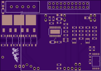
ECU Top.png
ECU will be about the same size as the original ignition unit 2-5/8x1-7/8" (and of course replace it).
Inputs: VR crank, optical cam, head temp, intake temp, TPS, barometric pressure, fuel pressure
Outputs, 2 injectors, 2 coils, fuel pump.
Integrated 14Point7 Spartan 2 OEM Wideband controller.

EDIT:
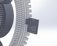
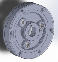
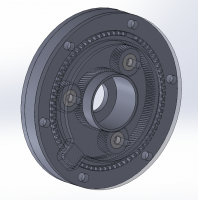
Sensor.pngFront.png Back.png
Speeduino has a unique capability. It can us a single missing tooth wheel at cam speed.
So I developed this last night and this morning.
A 2:1 planetary gearbox, and a missing tooth optical sensor.
As everything is keyed alignment is extremely easy.
This replaces the whole timing assembly on the DOHC.
This would be printed on an SLA printer, specifically the Elegoo Saturn when it becomes available in November.


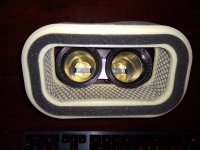
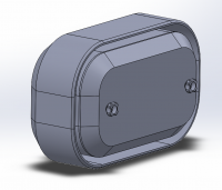
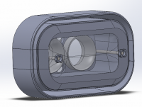
TB.jpg Filter 3.jpg Filter.png Filter 2.png
3D printed intake boots, made of nylon, a fairly high temperature rated plastic.
 
Last edited:
Post pics and any info you have. Dyno numbers with and without would be also a nice thing to have. I am sure someone would be into this. This would also need to include a o/2 censor, would it not?
 
I'm 2-3 weeks away from a running bike.
A wideband O2 sensor would be needed for some setups (and for anyone interested in tuning).
However the ECU doesn't need an O2 sensor to run.
 
Just a universal inline one. I have a GSL392 for testing, but I'm going to try and find a smaller one.
It will be electronically regulated, so return-less, and it'll run at a vary low speed at idle.
 
I've been interested in FI stuff a while. I was actually thinking of a similar project on a different bike.

I am curious why you have separate cam and crank sensors. The ignition on an XS is timed off the cam anyway.

Also - isn't Speeduino supposed to be able to read VR pickup coils?
 
Somebody better check that tach gear ratio before simply assuming it works...........some universal fuel pumps do NOT like to be turned over slow, they overheat. Needless to say the motor likely needs to be fuel cooled. (EDIT) I see the test one is.........

The engine has to turn 2 revolutions to get 2 cylinders to fire. That is 2 TDC points on each, without the cam sensor to show which TDC is on compression the crank sensor will not differentiate between the 2 TDCs, the other one being at the end of exhaust where ignition does nothing. The cam sensor also locates which cylinder is #1 if the crank wheel has no cutout or missing tooth to show it.
 
Last edited:
I've been interested in FI stuff a while. I was actually thinking of a similar project on a different bike.

I am curious why you have separate cam and crank sensors. The ignition on an XS is timed off the cam anyway.

Also - isn't Speeduino supposed to be able to read VR pickup coils?

The DOHC is timed off the crank, the coils fire twice per rev.
"Speeduino" is just firmware, you need a VR condioner IC, I'm using one for the crank, and optical encoder for the cam.

Somebody better check that tach gear ratio before simply assuming it works...........some universal fuel pumps do NOT like to be turned over slow, they overheat. Needless to say the motor likely needs to be fuel cooled. (EDIT) I see the test one is.........

The engine has to turn 2 revolutions to get 2 cylinders to fire. That is 2 TDC points on each, without the cam sensor to show which TDC is on compression the crank sensor will not differentiate between the 2 TDCs, the other one being at the end of exhaust where ignition does nothing. The cam sensor also locates which cylinder is #1 if the crank wheel has no cutout or missing tooth to show it.

No need to be a smart ass.
Yes you spotted the mistake, the ratio is 2.5:1 (I had thought 5:1 but that's from the crank), I will need to add some gearing to bring that to 5:1 or something else even.

As for the pump, did it occur to you it would be under almost no load when the engine was at idle?

If you had read my post you'd know I'm replacing the crank wheel. Specifically with a 36:1 Speeduino normally would be able to run in wasted spark with just crank, however it can't on this engine configuration, hence the cam sensor. That will also allow sequential injection.
 
The DOHC is timed off the crank, the coils fire twice per rev.
"Speeduino" is just firmware, you need a VR condioner IC, I'm using one for the crank, and optical encoder for the cam.

I remember seeing Speeduino having an add-on module for that.

In general, I am super interested in how this pans out. Way too often people abandon FI projects.
 
Not trying to be a smartass, when I get there people know it. Because I suggested something about tach drive?

'As for the pump, did it occur to you it would be under almost no load when the engine was at idle?'

Maybe. High rpm fuel pumps do not usually slow down that much, the cooling comes from the amount of fuel going through them, drop that to hardly any and they get hot along with the heat that comes from them moving so slow anyway. Even the so-called returnless ones commonly can bypass fuel by shunting it off of spring checks to keep pressure up and enough flow going to cool the pumps. It's how the fuel pump modules stay filled with fuel even with a low fuel tank amount.

My last sentence acknowledged your crank wheel if you read between the lines. Where were you going to get a cutout or missing tooth if not with your wheel?
 
Last edited:
The pump is being PWM controlled to regulated it's output pressure. 43.5psi is fairly standard.
So input power to the pump will be fairly proportional to the required flow.

Okay, I don't understand what you're asking about with the crank sensor.
Maybe it's just because I've had a few drinks this evening.

The stock crank wheel is a single tooth with two sensors.
I plan to use a 36 tooth (1 missing) wheel (plasma cut piece of steel) in it's place as that's an easy swap.
That gives me my crank pulses. If this was an even fire engine then I could run efi with only that (wasted spark).
But as it's odd fire so I'll need a single tooth cam sensor.
The easiest would just be a hall sensor above a cam lobe.
But as I was planning to make this available to other people I cam up with a way to run it off the tack cable.
It's 2.5:1 if I up that to 5:1 and use a 5 tooth encoder I've got my 1 pulse per cycle.

Speeduino looks for a pulse from the cam, then syncs on the next missing tooth on the cam sensor.
It exclusively uses the crank sensor for getting exact rotation.

I remember seeing Speeduino having an add-on module for that.

In general, I am super interested in how this pans out. Way too often people abandon FI projects.

Ya the official board has a socket you can replace with a dual channel VR conditioner.
The main board has the circuitry for hall sensors or optical.

I designed my own Speeduino board, (it's just over credit card sized) and ordered them from JLCPCB Thursday, I'll have them by next Friday.

My last EFI project was a 3000gt, until it spun a bearing it was happily running a custom Megasqurt board.
But I refuse to say how many half finished projects I have.
 
Updated the second post.
Instead of running gearing off the cam I've decided on a possibly more complicated to design, but easier to install geared crank sensor.
 
Any time you run a planetary you have to have input force to turn the gears and enough output resistance to continually force the planets to spin or the planets drop off spinning to simply be part of the main input force driver. The output quits outputting at the modifed speed to turn as one with the driver too.

It's not real clear where your output resistance is there. If just the driven disc running at half speed it likely will not be enough,
 
What are you talking about. No that's not how planetary gears work.
Planetary gear-sets have three input/outputs.
Sun, Planets (on a carrier) and ring.
A common configuration is to use one as an input, one as an output and constrain the third (many hybrids actually use two as inputs and the third as the output).
Automatic transmissions use clutches to constrain one to change gears.
Just about every cordless drill out there has the ring attached to the case, the carrier as the output, and the sun as the input.
In my setup the Sun is attached to the crank, the planets are fixed (on bearings) and the ring spins.
With a tooth ratio of 2:1:4 and this configuration you get an overall ratio of 2:1 from the sun to ring.

bike-cam-sensor-gears-sim-halfsize.gif
 
Last edited:
My point is you still have to have resistance at some place to make it work...........your 'constraint'.

You are right, they can be used 3 ways. I'm getting old.

Your drawing was incomplete, now that you mention the bearings then they will make the resistance mounted solid. I DID say it was not real clear did I not? You complicated the pic by showing double planets in pairs on dual helical rings too.

I work on ATX all the time.
 
Back
Top