Field Coil wiring question, ground or keyed power?

Spitfire_X24

XS400 Addict
Messages
124
Reaction score
28
Points
28
Location
Edmonton Alberta
Hi all, been away a while, very busy summer and very little progress on the bike, just getting going on the rewire, and ran into an issue with how to wire the field coil of the AC generator. All of the wiring schematics for bikes with the points style ignition with no TCI show the green wire running to the regulator like on all models, but the other black wire coming off the field coil goes to ground. On this bike, it switches from black to brown at the connector and goes to keyed power not ground.
I’m building my own harness using Drewpy’s steps and I don’t want to mess this up. I’m going to wire it as it is, with the black wire going to keyed power, but every pre-TCI setup I see has it going to ground. Just seems odd is all, there is no schematic in the Haynes manual that matches my bike completely. It’s like a mix of the 1979 US XS400F model, which it is, and the newer G models.
Has anyone else run into this?
 
So I think I got this sorted out, but now I'm scratching my head on whether or not my bike should have both a Light switch and a Headlight relay?
There are no other schematics with this setup, yet my bike has both.
 
Alright, I found a schematic that has a similar setup to my bike physically, it's the XS400-2E Schematic on page one of the Yamaha XS400 Wiring Diagrams thread. Although the Relay in that schematic is called a "Turn Relay" it is wired the same as my bike. It sends power to the two position Handle bar switch to turn the lights on or off.
The way I understand it, with the switch off, you start your bike and as soon as the yellow wire from the Generator to the relay gets power it closes the contacts in the relay, and supplies power from the red and yellow (R/Y) keyed power from the fuse box to the blue and black (L/B) wire which then goes from the relay to the handle bar Headlight switch, that wire also runs directly to the HI/Lo Dimmer switch, which means that there is already power there... before you turn on the switch. Oddly, the Red/Yellow wire also goes to the handle bar Headlight switch....It's doubling up the circuit? Not sure of the point of this?
Unless I'm reading the schematic wrong, but I went so far as to compare it to the circuitry on my bike currently, and that is the way it is set up. I even manually tested the relay, and that is how it works. Can someone explain this to me?
http://www.xs400.com/attachments/xs400-2e_wiring_diagram-jpg.3855/

Thanks for your help.
 
And just as a note, there are no Diodes in this system unlike the XS400H / SH models which have the white wire coming from the Generator with the diode in it to the relay...
 
XS400_1979_wiring_diagram_ignition_circuit.jpg
XS400_1979_wiring_diagram_headlight_circuit.jpg
XS400_1979_wiring_diagram_brake_and_signal_light_circuit.jpg
XS400_1979_wiring_diagram_charging_circuit.jpg
 
Alright, I slightly modified and broke down the entire wiring system on my bike. I started by moving the Ignition Switch towards the back of the bike. I removed the Headlight relay, the way it was wired, as soon as the bike fires up, the relay closes a circuit that runs the wire to the switch. I'll just leave the switch off until the bike is running, same difference, just manual, but less wires. Other than that, it all seems to be in order.
The schematics above should be a good easy to ready guide of anything on this bike now going forward. If you wanted to remove the electric start, there's your guide.

Cheers,

John
 
Hey John, I’m having some problems with my field coil and was hoping you could help lead me in the right direction. I picked up a 1980 XS400 and scrapped all the wiring (it was a mess). I rewired the bike with bare bones just to get it to run. I got the bike running good but when I tested the voltage of the battery when the bike was running, it was putting out a mere 12V. I finally started to learn about the field coil (I didn’t know about field coils before this) and I realized I didn’t have any power or ground running to my field coil wires.

I will try to explain this the best I can…
There are two wires coming from the field coil Green and Black. When the wires get to the connector, the Green wire stays Green, but the Black wire turns to Brown. So now there is a Green wire and a Brown wire going to the regulator. From the regulator, there is also a black wire that goes to ground.

I got some alligator clips and hooked up the Green wire straight to battery positive. I then hooked up the Brown wire to battery negative. Now my field coil “excites” and is on (and the magnetism can hold a razor blade to the crankcase). Now when I run the bike, I’m getting 17V at the battery! As good as it is to know that my stator and rectifier work (my regulator and rectifier units are separate), I just now need to get my regulator wired so it works correctly. I’m trying to think how I can do it but I can’t think of anything.

When I look at the wiring diagram you posted above, it shows a brown wire coming from the field coil which goes to positive. Then I see a green wire that goes from the field coil, straight to the regulator. It would only make sense to me if that green wire gets its “ground” from the black (ground) wire that goes to the regulator. But the problem is when I try connecting positive power to my green wire, and having the black wire on the regulator grounded, my field coil just simply doesn’t work.

I also want to note that I have 2 original regulators (one that came with the bike and one I bought off eBay). Then I also have a brand new combined regulator & rectifier unit. All of these show the same results when plugged in.

I think I’m just missing something really simple but I can’t figure it out. Any help would be great, thanks
 
Xander, I think it depends on the style of regulator you are using whether it regulates the field via the ground or via the power. I think the default XS400 regulation is switched 12v power to one of the field windings and the negative wire to the regulator (green). Then the regulator switches the ground on and off to regulate power output. I'm pretty much working through this issue myself playing around with both a VR125 Dodge VR and a VR115 AMC/Jeep one. I was getting good idle voltage from the VR125, but spiking up over 16.5V at 3500 rpm and up. I get nothing from the VR115 though.
 
Xander, I think it depends on the style of regulator you are using whether it regulates the field via the ground or via the power. I think the default XS400 regulation is switched 12v power to one of the field windings and the negative wire to the regulator (green). Then the regulator switches the ground on and off to regulate power output. I'm pretty much working through this issue myself playing around with both a VR125 Dodge VR and a VR115 AMC/Jeep one. I was getting good idle voltage from the VR125, but spiking up over 16.5V at 3500 rpm and up. I get nothing from the VR115 though.
Thanks for your reply. If I understand this right, you’re saying the field coil should be getting constant power through the Green wire? And then the only ground will be the black wire that comes off the regulator?

It makes sense to me that this should work and that the regulator will then regulate voltage by “shutting off” the ground. But when I do this by only suppling power to the green wire, and grounding the regulator via the black wire, the field coil doesn’t energize at all.


The picture below shows the kind of regulator I have. It’s the original one and I have two of them that I’ve been testing. I also have a brand new combined regulator/rectifier and all three of them are doing the same thing.
 

Attachments

  • AB229C67-A865-4C6B-8865-2E987FC2CC3D.jpeg
    AB229C67-A865-4C6B-8865-2E987FC2CC3D.jpeg
    79.6 KB · Views: 120
Actually reversed, at least on my 1978, the field is provided switched 12v power via a brown and the regulator grounds the green. While the bike was running, I had unplugged my regulator and put battery ground to the harness connector green wire and got the full alternator output.

I should elaborate, the +12v power to the field is from a different connector that also connects the neutral switch and oil pressure sender, not the regulator itself. On the regulator wiring, brown is switched battery power, green would be the field regulated ground and black is negative battery or ground.
 
Well, a few days ago I tried a different regulator that I had and it worked great. I used alligator clips and wires to hook it to the bike. It’s from an XS360 and has an adjustable screw. I got a solid 14.5 volts from it and I was absolutely stoked! I went back today to permanently wire it in and decided to check it one more time with alligator clips. And of course it didn’t work. I remember exactly how I had it wired up but I still spent over an hour trying to wire it up different ways just in case. It’s like this bike has a mind of its own. I’m at a lost with it right now. The only thing I can think of is to try the R292 that everyone is talking about. Does anyone have a picture of it? I’m having a hard time finding one on the internet.

Any other words of advice would be great. I just don’t understand how a regulator can work perfectly one day, then sit all comfy on the bench over the weekend, and then just not work at all when I plug it in again.
 
Not sure about it working one day then not another but the XS360 regulator works by controlling the + supply voltage with the other field coil wire going straight to ground, as opposed to the electronic regulator you posted above where the field coil connects to +12v directly and the other wire grounds through the regulator.
 
Not sure about it working one day then not another but the XS360 regulator works by controlling the + supply voltage with the other field coil wire going straight to ground, as opposed to the electronic regulator you posted above where the field coil connects to +12v directly and the other wire grounds through the regulator.

I’ll try putting positive voltage through it when I get home. I remember vividly regulating ground when it was working last week but I suppose I could be wrong. I’ll let you know.
 
Well, I wired it up to regulate positive voltage but still nothing. Then I spent the next hour trying every combination with the regulator and wires. I was able to achieve different hums and clicking sounds from the regulator but nothing from the bike.

I was reading about voltage regulators on cars and someone said that voltage regulators are so easy to fry you can do it just by unplugging a wire while the car is running. I don’t know if that’s true or not but it could be possible that last week I unplugged it while the bike was still running and that’s why it’s not working anymore. Anyways, I want to try the R292 but when I look it up it says it’s from a 70’s International. And in some posts I’ve read, people say they picked up the R292 from an autoparts store. If the R292 really is from a 70’s car I can’t imagine they still carry it in the autoparts stores. So if anyone has pictures or more information on where they got their R292 regulator, that would much appreciated, thanks
 
Xander, Like you I have also been fighting a regulation issue. I had bought an AC Delco Gold version of the VR-125 (the 80's Dodge VR) and it worked initially, though topped out at 15.2 volts above 3500-4000 rpms. I felt that was just a little too high but was going to just run with it for the time being. Then a few days later I re-checked my voltages and now at the same RPM I was seeing 16.5 volts, and if I blipped the throttle, I could make 18 volts. :eek: 
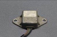
So I bought the VR115 (the r292 AMC\International one) but never got to wire it in as I found the difference between the two was positive vs. negative regulation. I was going to have a go at switching the field coil polarity but winter weather and snow put that off. After looking at the AC Delco VR, I saw some melt marks in the epoxy sealed backing...it had fried which was why my volts went high, I confirmed it was internally shorted to ground. So I bought a TransPO Heavy Duty adjustable version (I think C8313) from AdvanceTruckPartsUSA.com (their part num is W112101) and plugged it in. Now I have 14.2-14.4 volts revving the bejeebus out of it and 13.5-13.7 volts at idle. I didn't even touch the adjustment screw/pot on the backside. So I'm going to leave it at that myself.

I see you are in Utah. I'd be happy to send the brand new AMC/International VR I have here to you for the cost of shipping. I did already clip off the AMC harness plug end so I can't return it anyway. PM me your address (or at least your city/zip) if you're interested and I'll respond with the USPS shipping cost then you can decide.
 
Back
Top