LED Brake Lights! (Pictures and Poll!)

Are LED's the best thing for these anemic charging systems!?


  • Total voters
    20
  • Poll closed .
The turn switch does not swap polarity. It's just a switch that is center off. Push it one way it lights the left side, push it the other and the right side lights.
When you swap to LED turns the stock flasher won't work. Replacing the stock flasher with an LED compatible flasher.
If you have a single indicator in the dash it lets current flow so both sides light.
You need to add diodes between both sides of the turns to one side of the indicator, ground the other lead.
Leo
 
I feel like there's some mistunderstanding here. I'm not trying to address the fact that it doesn't flash. I ordered a new relay which should fix that.

is that my rear, right turn signal bulb gets light with the normal bulb, but not with the LED bulb, the other 3 signal bulbs work fine with both. But the rear right one won't light up at all.

will switching the wires in that socket still work for this?
 
http://www.xs400.com/forum/searchgo...0.com/forum/usercp.php&ref=&ss=2450j627276j11

have you shifted though these threads? perhaps one person had that symptom, noted it, and fixed it. I am not sure what to think? is the led you have the right number? 1156 verse 1157? (I don't remember which is which today) Verify you have the right one in the right socket, one socket has a push deep down, verses a slight push in, and twist. (both needs a twist. The Diode thing that was mentioned before? That is neccessary for the older Yamaha's Reason is, the grounding system. When you turn left, the bike signal is expecting feedback via a turn signal bulb. So the bulb turns out to the ground point, and then it will back feed electricity. I dont' remember if my test to resolve that included pulling the bulb to see if that resolved an issue. ThenI ordered the Metric diode conversion kit, from superbright led (i think, should be posted) Hope that helps. I remember attempting to find out where those lines grounded out at, so I was following the continutiy, and at every twist, and turn, I was getting a short, until I pulled the signal bulb. The solution that yamaha went with going forward, was two light bulbs. But you and I have only one turn signal light bulb.
 
Ya i've combed through all those posts, a lot of people complaining about all four flashing, no flashing, all four staying on, etc. but not just one bulb.

its definitely not my bulb, i wish i knew the reasoning behinds XS400NJ's solution, but i'll try it this weekend and let you guys know. otherwise, i guess ill just have one signal using a normal bulb.

this makes me really hesitant to start my HID conversion...
 
You know a simple check, is the contacts. Sometimes, if this is a turn signal, there may be 2 contacts that is not making contact. With the power off, you can use a flat screw driver to twist the contact thing back to its position. (since I don't remember if you light is a double filament or single contact. If you are getting the majority of the lights working, with only one original light, That is still saving you energy that is helping minimize the electricity expenditure when braking,you probably not even notice the dimming of the headlights with just one original light bulb.
 
Hey Armstrom,

ya one normal bulb isn't bad i guess, hopefully installing the new relay won't mess with how the 3 new led bulbs flash.
 
The issue that has been expounded on relentlessly, and incorrectly marked Successfully solved by me, was the Timer feature. There is a thread marked Success fully got the flasher turn signals to stop after x-amount of time/distant/speed... I was mistaken, and so was the individual that started that thread. I still hope to spend some time with a decent monitor, and see what type of signal is being sent from the tach, and see if we can come up with a new type of auto cancel feature, for us LED users.

So here is the factoid, (in case you missed it) Right now, if you have everything working per OEM restored... The flasher meaning turn signal on an flashing one side or the other.

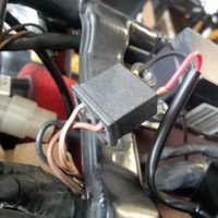
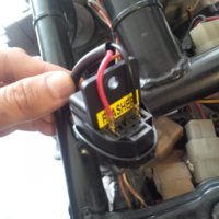
Once you switch out the factory relay, you will lose the ability to have the signals turn off on their own. Is it a big deal, nope, but it is something that I tend to "not worry about" when there is other traffic concerns are going on. So my flashers tend to flash for a little bit, till I finally do my look around to see if I am being followed, getting a ticket, or notice the speed/tach readings. Then I will turn it off.

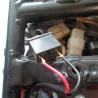
The original turn signal off module is called a Autocancel relay type of device. It takes input from the Tach. Then when one of 2 or 3 conditions is meant, Tach over x amount of RPM's for x amount of seconds ... So that will will send a signal to the relay to turn off the flashing. That device is looking for the combined total of watts being used, to judge when the flasher is on. So now that we have switched to energy saving LED's, we are not using 3.xx amps/watts (whatever its looking for) X2 (front and back) left or right side.

So I think ultimately your still have the energy savings features your looking for, one original bulb verses 4. So your saving 2 to 4 units of electricity. Which I think for most us, we want the bike so that when you hit the brakes, you don't notice the power draw, when the brakes lights are on.

So the next thing(maybe I missed it) The easiest, with no implications upgrade, is just swapping out the LED's into the brake lights.
 
I've also been annoyed that we lose a feature by "upgrading" to LED lights. I hooked my multimeter up to the pin in the auto-cancel connector that reads the speedo signal.
I was able to confirm some good info on XS650 that it pulses to ground for each rotation of the front wheel (not 100% as I have no center stand and couldn't spin the wheel freely).

The next step will be ordering some matching connectors and then wiring a compact arduino microcontroller to monitor all the pins in the connector.
Once the function of the auto-cancel can be replicated I'll add a relay to the arduino and combine the auto-cancel and flasher into one unit.

I've done some coding and electronics and none of the functions are terribly complicated.
Nano arduino boards are very compact and can be very cheap. The whole thing could be done with under $20 in parts.

Then my thoughts jump to logging functions. Since we're monitoring wheel RPM's we can easily add a computerized odometer and code alert functions for each service interval.
Add a connection to monitor motor RPM and we can log performance, mileage, quarter-miles, etc, etc. Could probably do some math to extrapolate torque and other performance data for the bike.

But that's all beyond the scope of the flasher/auto-cancel functions. If I can get my bike running to free up the spare time, I might be able to get the auto cancel going by next summer. :)
 
I was hoping for the same, with college, 2 cars, 1 bad clutch, 1 with a clutch going bad, full time employment, and a family, and (insert something else extended family with med issues) I would also, get that working right.

I did find the diagrams either in the 45 meg download manual, or in the back of the 82 DOHC has a diagram for that model, I don't think its anything different from the 80/81. (sticky Manuals, chapter 6, 10 meg file)
 
got the LED signals to blink perfectly with the new relay!

I wanted to include pictures for this because i couldn't find any before, and i was super confused on how to do this even after reading.

i got the LS1 Flat LED Flasher Relay from SuperbrightLEDs, the one that's mentioned here a few times.

Where i was confused was on the instructions on how to install it. So ill clarify in case there are other confused like i was. Take the white plastic plug piece off the wires, i used a needle like object to push in the "tooth" that was holding it in place (youll see what i mean once you buy it).

I then opened the "tooth" part of the wire end so that it would be more secure in the stock socket for the relay. Otherwise, i'm almost positive that vibrations will pop it out. I then took electrical tape and zip ties to secure the relay and the socket together.

and it works beautifully, with the 3 LED bulb turn signals i have in and the one stock one that wouldn't work with an LED (separate problem from the relay i believe),

but while i was there i noticed the wire leading to the signal that wouldn't work with the LED bulb, was frayed (picture), i cleaned it and wrapped it with electrical tape, but still no fix. any suggestions aside from replacing the whole wire?
 

Attachments

  • IMG_20141026_091457.jpg
    IMG_20141026_091457.jpg
    231.6 KB · Views: 336
  • IMG_20141026_091439.jpg
    IMG_20141026_091439.jpg
    210.8 KB · Views: 317
  • IMG_20141026_091447.jpg
    IMG_20141026_091447.jpg
    282.5 KB · Views: 340
  • IMG_20141026_092206.jpg
    IMG_20141026_092206.jpg
    214.9 KB · Views: 322
  • IMG_20141026_092553.jpg
    IMG_20141026_092553.jpg
    191.6 KB · Views: 352
  • IMG_20141026_092856.jpg
    IMG_20141026_092856.jpg
    234.3 KB · Views: 342
Jonjkim, I just tried to find out what type of bike you got? everything time I seen a signature line with a bike model, It wasn't yours. everyone else on this thread has a model number in the signature space. All I know for sure is my flasher was rectangular, compared to yours. So does that make your bike newer or older?

That last picture, You should be able to get a resistance reading from the connector bundle, (under the seat) to the end of the run.(where the light bulb sits) Then do it to the good side. The numbers should be good, if they match. other wise you will have to replace that wire. Just that wire. I like to use a self sealing Vinyl tape. Perfect for every condition we can put it thou. I usually get the 10 foot one from the local store. various colors.

http://www.menards.com/main/electri...licone-self-sealing-tape/p-1914287-c-6482.htm
 
Hey arfstrom,


1977 xs360 (updated my signature, but i guess it takes a while to apply)

my bad, i'm pretty new to the forum and up until now stayed in the one thread i created for the problem i had before. haha

good point on reading the resistance. I'll give it a try. i had re-wiring work, so if it is that i may just leave it until im ridiculously bored.

thanks!
 
its definitely not my bulb, i wish i knew the reasoning behinds XS400NJ's solution, but i'll try it this weekend and let you guys know. otherwise, i guess ill just have one signal using a normal bulb.

The reasoning is simple, if regular lamp works and LED lamp does not work in the same socket there are only three problems I can think of:
- LED is bad (but you already checked that )
- contact is bad when you insert LED (I assume you checked that)
- polarity is flipped - that's what I suggested to check.

You can check with voltmeter where is the '+' and where is the '-'.
 
you've mentioned Polarity which has been mentioned before.

do you mean the wires feeding into the socket are switched? i was playing with it after the first suggestion, but i assumed if it was switched it wouldn't work with the normal bulb. is that not correct?
 
Normal bulbs are not polarity-sensitive. LEDs usually are.
They are also more sensitive to voltage drop. A bad connection may still light up a regular bulb but drop the voltage below the LED's lower limit.
 
I see,

ya that's what makes me think it was the frayed wires to that specific signal under my fender (pictures in my upper post).

I'm find with one normal bulb.
 
I literally just took a look at it,

so of the two wires, one is solders to the spring that holds the bulb and the other is in the socket. Not gonna lie, i'm afraid to take those apart.

and yes it drives me insane!
 
Back
Top