TimmyT
XS400 Addict
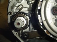
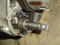
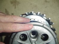
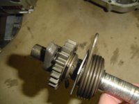
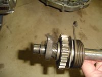
1978 xs400E in progress. Ok so after my rewiring the stator and field coil I found out after pressing it all back in the field coil has failed or my new wiring got pinched somewhere. So what the hell try again. I figured I can check my gasket and improve it along the way and see for anything that passed me by ... such as the exhaust gaskets I never did. So along the way I inspected the shift rod, gear selector, and clutch as well, as well as the kick start and gears. All of which seem to be within spec. The service manual has enough detail for a mechanic which I am not, and some bad black and white photos to back it up. So Upon opening it up there are a few things that elude me before I close it up again which I want to tend to cause I don't want to drain the oil and do it all again. All parts so far have been cleaned up and re oiled. I removed the oil pump but the cover bolts are far to tight to open and inspect the inside for wear or damage, should I worry much about this component failing if everything else checks out. The kick start return spring seemed a little loose and I found a way to set it so the spring is tight with some good action, the only thing I was not sure about is the piece of metal at the back that moves counter clockwise with the kick turning action (it is part of the main shaft). Does this piece need to be resting on the side of the lip or the top of the lip inside the crankcase? If I rest on the top of the lip I worry when kicked if it will damage the engine, I would guess it rests on the side as a stopping point for the return or just floating in there not resting on anything. It only turns about a quarter turn within the housing but seems like it can be bad news if I got it wrong. The field coil is not magnetizing so maybe it has completely failed on me, likely the source of my voltage reg issues. will the coil itself actually ever fail? or just the armature? I tested my NEW rr38 and the rectifier portion is not testing correctly, but the old one checked out so Ill go back with that. What I don't get is the voltage regulator portion of the rr38 does not test in spec for my requirements, however I am getting the same funky readings from the old voltage regulator as well. Im starting to think neither is meant for my bike and I should be looking for an older mechanical voltage reg (one that controls ground) rather than these solid state units.
This time I am going to get it right, I took photos if anyone need to see what im talking about, in the meantime I am looking for advice.
Also if anyone has a Yamaha rotor puller tool to lend or sell as well as a mechanical voltage regulator for sale, or maybe (pending) a working field coil for sale then drop me a line. I have a few spare parts available for trade or just good ol cash.
Also curious about the gaskets and the overhang the old ones have on the inside of the crankcases... is it possible to just use gasket maker and seal the outside of the cases without incident or do they need to be oversized for a reason? Not even sure if mine were original or made from a kit but I would imagine they were original. Ultra Copper grade high temp gasket maker is what I went with. Apparently 1.2 mm thick or so and handtight screws until it oozes out the sides a bit, wait 30 min and 1/4 turn tighter, then after an hour or two another quarter turn then after 24 hours dry time torque to spec. Anyone have any thoughts pro or con on these gasket makers or should I look into getting a real set? thanks in advance fellas!
 With the clutch when you put it together did you line up the two arrows? If not it will not work correct. I posted also a pick on how the kick start should be installed.