Yet another charging issue...

Well, now I'm at a complete loss. I put my brand new stator and field coil back together last night, started her up and nothin!:banghead::banghead::banghead::banghead::banghead:

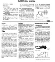
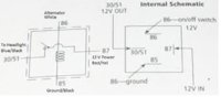
I checked the regulator and I couldn't find any continuity with ground (and yes, the reg box is grounded). WTF? It's brand spanking new. VR125 from O'Reillys with a new pig tail. I swapped connections to make sure the blue and green wire weren't switched, still nothing. So I bypassed the regulator and grounded the green wire. Razor blade stuck no problem so the field coil is definitely good. Although every time I grounded the field coil the bike bogged down a bit. Is that normal?

So I thought the reg was bad. I figured okay so if I test the charging system with the reg bypassed I should get 14+ volts. No luck!! :banghead::banghead::banghead::banghead: It only jumps up about .1 V (11.15 to 11.25). I tried to get the AC voltage from the stator but I don't have enough hands for the probes and grounding the field coil.

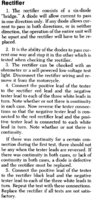
The only parts that aren't new on this thing are the wire harness and the rectifier. Is it possible that the rectifier can pass the continuity test and still be bad? If that is the case, could that be why the reg isn't working? I can't believe it is because the reg should be powering the field coil at 11 volts. This is crazy!!
 
Is it possible that the rectifier can pass the continuity test and still be bad? If that is the case, could that be why the reg isn't working?
Testing by the numbers for the rectifier, is to Use OHMS, and then your testing both directions. The need is to make sure that the current doesn't go backwards.(keeping the current DC)

Okay, I copied and pasted the electrical stuff for testing, into hopefully into a one pager. I left the page numbers on the existing, to help find the original, just incase there is an oversite.
 

Attachments

  • x400oldVoltageRegulator.jpg
    x400oldVoltageRegulator.jpg
    181.7 KB · Views: 349
  • x400oldRecifier.jpg
    x400oldRecifier.jpg
    116.9 KB · Views: 364
  • Electrical system.png
    Electrical system.png
    202.5 KB · Views: 431
Good news and bad news. The rectifier works fine so I think I'll keep it on there. Bad news, that wasn't the problem. Upon some more continuity testing, I discovered something interesting. The wire that tees off to go to the headlight was grounded. Traced it to one of the bronze relays under the battery.

I'm not sure what is going on there. One of the relays turns the headlight on as soon as the key is on, and the other doesn't work at all if I swap them out. I'm going to google the relay terminals and try tying in a universal relay instead of those. I have already replaced them once. Who knows...:shrug:

The VR is still fried. I'm not sure if it was DOA or if I fried it playing with a bunch of wires all the time because I don't think that thing has ever worked. I'm also surprised that sending the stator voltage straight to ground didn't fry anything.
 
Picked up another vR and relay. The universal relay worked great and now the headlight operates as it should. The new voltage regulator worked for about 3 minutes then just quit. To top that off. I picked up a dash volt meter and connected to the battery for constant analysis and to free up my meter. At the rectifier my voltage is right where it should be 12.5 at idle and ramps right up. At the battery, it only shows 12.5V when its 14V at the rectifier. This is with the VR bypassed and no headlight BTW.

So somewhere, I have a 1.5V drop between my rectifier and battery? WTF?!?!?!?

So I guess somewhere I must have a short in the wiring that is causing a large voltage loss and my VR to take a dump almost instantly. Any ideas?

Edit: I'm starting to feel like Scorpio:(
 
Last edited:
Which relay did you get?

one relay, keeps the headlight off until the stator is making power.
other relay ensure that the bike is in neutral, or clutch pulled before you try to start it. (some models will watch the kickstand postion.)

The headlight one has the white wire going to it. from the stator, providing the headlight its own phase of power, so that the 55 watts, doesn't impact the rest of the systems. (notice it has its own diode, for the AC to DC conversion)
 
I just used a standard 4 pin relay. The single phase of AC power goes directly to ground. The only thing it does is excite the coil when the stator is running which causes the 12V DC red/yellow wire to connect to the blue/black. The headlight doesn't actually run off of AC current. The AC only switches the relay closed. But that problem is fixed now. My big problem is why my system is smoking my reg within a few minutes and my battery noy being the same voltage being produced from the rectifier. I have a serious issue somewhere. The kind that gives you the cold sweat and fear of a rewire.
 
My big problem is why my system is smoking my reg within a few minutes and my battery noy being the same voltage being produced from the rectifier. I have a serious issue somewhere. The kind that gives you the cold sweat and fear of a rewire.

Is the Reg grounded? (if you seen my pics in the I ran a ground wire from from the bolt that I bolted down to the frame, and ran that into the ground wire into the bundle)

is any of the wires testing bad, in that its grounding out when it isnt suppose to?

PS the last parathesis in previous post eluded to the diode switching power from ac to dc mode previous to getting to the relay:doh:
 
Well I had a few theories through my subconscious haze last night (its when I do my best thinking:shrug:) Anywho, I agree with you Arf, its got to be a bad connection somewhere. If a wire was shorting, it would be blowing fuses like crazy, not prducing large voltage drops. That could only mean a bad ground/connector somewhere.

It would also appear that the PO replaced that white wire to the relay. I haven't been out yet this morning to check if there is a diode on that wire but what would happen if there isn't one? Would it fry the relay quicker or pull more power away from the battery?
 
It would also appear that the PO replaced that white wire to the relay. I haven't been out yet this morning to check if there is a diode on that wire but what would happen if there isn't one? Would it fry the relay quicker or pull more power away from the battery?

Think of the stator. when I say phases, that just means that the output, is created on each of the wires coming off the stator, in our case we have 3 white wires, thus 3 phase system. The stator only creates AC power. so anywhere you see a white wire (one exception) you should be using your AC side of the multimeter for testing. So generically the 3 white wires goes to the recitfier, the recitfier has 6 or diodes. A diode only lets the energy that was created, to go one way. So AC is energy going back and forth thousands time a second. You put a diode, and it eliminates any backward flow of energy. now on the other side of the diode is DC, energy that only goes one way. Now I say energy just cause its is energy/power. The stator power I suspect it can create a large amount, someone mentioned it creates up to 75 volts a/c, I don't know for sure) I do know that the recifier will drop the power to 12 volts DC, and it has 3 paths to keep the power at 12v DC. then the VR will sense a drop which it will kick the field coil to on, which will give a power boost to the rectifier.

That exception i mentioned? There is one white wire that splits off in the harness, and goes to that relay that does have one doide. if you have the parts schematics, or look on line at a oem parts, breakdown, under electric 1, you will see the diode available for sale. It is located under the tank, just at the split where the harness comes up from the battery zone, to the under the fuel tank spot. Look up Scorpio's ignition thread, He felt that was missing as well. There is some pics there, and stuff like that.

hope that helps, my lunch is over! chat later
 
I multimetered that wire with ground. I got continuity in both probe positions. That means that there is no functioning diode on that wire. Do I have to buy an OEM replacement or can I get a generic diode? Generics are way cheaper. The only thing I don't know is the requirements of the diode I need. I assume it needs to be 12 Volts but I don't know the amps/watts
 
Sure enough, I found where the diode was supposed to be and the wire was just soldered together. I just stopped by radioshack and picked up a 1N4001 Diode. That was the one someone else had on another thread. Hopefully this will work out like it should. I will hook it up, clean all the connections, and hook up yet another voltage regulator and see if that fixes things. I'm getting closer...
 
You know, even I forgot what a diode was for, till I started putz-ing with my bike, eventually with my long forgotten 9th grade electronics class, (seriesously long forgotten) Cars do the same thing, its just there rec is built into the generator, so its 12v DC comeing out. so I think alot of people, like your PO, just had no clue. Now to me, its easy, AC on one side, and DC after the Diode. So now that you there, Good luck. Unforturnately You might want to use clips until you can figure out which way to put it in. with my harness on th original, you get the oem diode, the male piece goes into the female piece, and same with the opposite side. now that the PO mess it up, you will have to guess which way your energy path is. So somesort of clip will make it easy to test it both ways with out soldering it into position. I suppose you could just put female ends on the harness wires, then the diode you got, can have the 2 male connections, then you can test it, just flip it, then put on heat shrinks when you have it figured out. (note I would still recommend soldering the gender parts to the wire your working when you got it figured out.
Tobie
 
After looking at your relay pic, I noticed the universal doesn't support added power to the headlight circuit via the added power from the white line. So what your generic one is doing is using the positive hand off from the stator spinning, which is enough to kick the magnet switch, then you are using headlights off of your battery, via the fuse. You still have the right path, to support, it, but I suspect the sooner or later your fuse will burn out.

With that said, I don't know for sure. is 12v from fuse, Black is ground. Blue is out put to the lights. White is from the stator. I always figured you would use a small amount of electricity to flip the relay(magnet switch) then use your primary power for the actually power draw, backed up with the battery.

Look at the safety relay, Yamaha broke that down to easy to read, then I assisted. Unlike your diagram, this one seems to be parallel. you see what I mean?

Unfortunately, I have yet to find a diagram (yet) Not that there is anything wrong with what you have. When I was troubleshooting the relays, I just swapped the two, like you, the head light turned on. I went back to the way it was, and I was fine.

Good luck, Tobie
 

Attachments

  • Enhanced Starter system.jpg
    Enhanced Starter system.jpg
    81.4 KB · Views: 424
So somewhere, I have a 1.5V drop between my rectifier and battery? WTF?!?!?!?

So I guess somewhere I must have a short in the wiring that is causing a large voltage loss and my VR to take a dump almost instantly. Any ideas?

Edit: I'm starting to feel like Scorpio:(

Assuming your wiring between the rectifier and battery terminal is stock, there is only one thing that can cause that issue. Resistance. Might want to check the connection at the battery, the connection at the bullet connector, and the connection at the plug connector.

Set your multimeter to read resistance and put one probe at the battery and one at the rectifier + terminal.

This is also a good time to think about a complete rewire. You'd be surprised how nasty that copper can get under the jacket after 30 some years.
 
Seriously though, your probably right. A rewire isn't a bad idea. Hopefully, I can make that a winter job though. I want to band-aid it for now so hopefully I can get a couple weeks out of it this summer.

I was thinking about the way the wiring is set up. The regulator doesn't go straight to the battery, it ties into the brown wire which then goes to the fuse box, then the ignition (in some roundabout way), back to the fuse box via the red wire, through the starter solenoid, and finally to the battery. So somewhere in this plethera of wiring, there is a bad connection. And somewhere in all this mess I'm sure it ends up in my rats nest of a headlight bucket just to piss me off. THATS JUST FREAKIN GREAT! Hopefully I can pinpoint it quickly with your multimeter idea. I will put one probe on the battery and work my way backwards from the rectifier with the other until I find it. Thanks for the idea.
 
Back
Top