Yet another charging issue...

:shrug: you got me on that one. A capacitor is typically for holding short term energy, and to be able to provide energy as needed. and typcially can not or will not hold energy in a off state.

There has to a PCB board person out there, who is ontop of this stuff?
 
I posted this issue to the12volt.com Hopefully someone there can answer my question and we can get this figured out. It would be really nice to figure this out then people wouldn't need to buy the OEM relay.
 
Doing a lot of research on the subject today and I've learned a few things. Our bronze relays must have had a filtering capacitor in them to maintain a DC Voltage. The AC voltage from the stator @idle is about 15 VAC. The in line diode of the white wire is a half wave rectifier meaning that voltage is being produced only half the time. This causes a normal relay to rapidly open and close causing a "buzz" and dim lights. What you have to do is put on a filtering capacitor to maintain a constant voltage in the system shown in the example below.

diode_peak_det.gif


This will cause the voltage to be maintained and look like this:

diodeimg51.gif


So assuming a 15V supply from the stator will yield ~15 volts DC half wave rectified. the 12V relay needs a minimum of 12V to switch closed plus a 1V safety margin, that gives us a 2V window to work with (Vrpp)

Vrpp=I/fC where I is current, f is frequency, and C is capacitance. I assumed a 100hz frequency (it would change depending on rpm though and I have no idea what that would be:shrug:) A standard 12V relay is about 90 ohm making the current draw 0.167 A. Solving for C gives us 850 uF (Farad). So I'm going to go back to radioshack and buy a 1000uF capacitor and rewire the wire to look like this (Squiggle is AC power source and R1 is the Relay):

070bad5eb27428f72d936dac0541d1c0.jpg
 
The stock relay has no capacitor in it. I've taken it apart.

Make sure you are using an electrolytic capacitor for this application.

For what it's worth, you shouldn't even need it in this application.

Why do you want to retain the headlight relay in the first place? Just curious.
 
Head light relays are nice especially is you are running a smaller battery. As it will keep the light off till the bike starts running/charging. I guess you could just wire in a switch for the head light. But then there is another thing to remember to turn on/off so you don't kill the battery:doh:
 
:agree: I don't have a smaller battery for now, but I do like the idea of keeping the OEM functionality and keeps the option available in the future. It also requires less cranking amps so it might help the battery last a little while longer. Lastly, I'm horribly forgetful and would probably never end up using a switch. I would either drive with it off or start it with it on. Not worth the potential ticket.

As far as the old relay goes. I have no idea how they got that relay to work with only a half wave current. They had to have done something to keep the circuit closed in between the voltage peaks. The new relay surely doesn't.

Another thing I read was to put a relay to the starter solenoid so when you hit the start button, the headlight shuts itself off but is on any other time.
 
It works because of the relay design. All it needs to see is the initial DC pulse to keep it latched. It doesn't care that the voltage moves to zero after that. If you didn't have the diode there, then yes it would turn itself on and off with the AC cycle.

Ever notice how if you blip the starter(without letting the motor start) that the headlight comes on and stays on?
 
BTW I don't know a lot about the XS400 wiring scheme as I completely removed mine and redid it from scratch when I did my build last year. But I do know a bit about electronics, as I design and build tube guitar amps-
9501265c.jpg


From what I've seen in online forums (not this one specifically) there is a lot of misinformation and confusion that gets thrown out there when it comes to motorcycle wiring. My advice is to keep it simple, and if you want to keep it functioning like stock, then use a stock part, and make sure the wiring is all redone as in stock. Will save you some headaches.
 
Well, to be honest, this whole diode/relay thing kind of got away from me. I initially thought that a normal relay would work, then the next thing I know I'm teaching myself electrical theory.:doh:

As for the old relay, I never noticed because the relay was shorted out and the headlight came on with the key.

So could you provide the circuit the OEM relay uses? That would probably help others out who don't know how the magical relay works.:wink2:
 
Sorry, looks liked I encouraged this one! I am glad that the knowledge was pushed further. So we can put it on the back burner, and hope one day the jap that decided to use that 3H5 relay, and or give up the diagram. I am sure it makes sense to one of them. (out of 6 billion of us on the planet) I used Sense again in this thread!
 
I'll draw something up after work tonight. I believe there was a jumper wire from the 12vdc switched side to the coil, so after the relay switched on the 12vdc clamps it in that position. It would not release this position until the key was turned to off.

That's just off the top of my head, I'll take a look when I get home and grab a picture of the internals for ya
 
Well, It worked in theory but not in practice. I never made it to radio shack so I just used the 4700uF capacitor that I had figuring that more capcitance couldn't hurt. When I atrated it, the headlight worked like a charm. After about a minute a plume of smoke went up and my capacitor was sizzling. I guess my assumption about the frequency of the AC current was WAY off. Oops. If anything, it would need a larger capacitance, which would be impractical. The 4700uF was already pretty large (about the size of the relay). I suppose maybe a solid state supercapacitor might work but then you may as well buy the OEM part.

Final Conclusion: FAIL
 
So wait, If its just a matter of a jumper, and there is a diode on the white wire to stop a back current, couldn't you just jump the white wire with the blue wire? The white voltage pulse would close the relay which in turn would charge the blue wire which would power the headlight and power continue to power the relay coil.

On a side note, I think I'm in for a complete rewire. I can't get more than 13.3 volts at the battery with the headlight off after soldering all connections between the rec and batter. I know the charging system is working and the battery is a brand new AGM battery so my wiring system is obviously losing voltage in the wiring. I could try to sift through all the horrible rats nest of wiring from the PO but I think its better to just start over.
 
I think that is my thought, the Diode, is created a one way shortly after branching off the 3 whites to rectifier. Then the relay is receiving voltage from stator, (direct no buffering, or other protection, outside its only DC.) My assumption, I am sure I have seen a literture that states the power line supports the headlight draw. So why couldnt the white line trigger the swtich, and then support the output line? Like you said
you just jump the white wire with the blue wire? The white voltage pulse would close the relay which in turn would charge the blue wire which would power the headlight and power continue to power the relay coil.
Our problem is we don't know if the fused line is going to support the headlights alone, and using relay, like you did initially, just as a device to sense when the stator is spinning.
 
Here is how the headlamp relay works, in a crude drawing done by me-

002DF6C8-75B2-4925-8817-41E191B07E7E_zps4r8wnvlb.jpg


SchemLampRelay_zpsbbeac444.jpg


The Yamaha engineers used this setup since it is the cheapest and easiest way to implement the 'no headlight at startup'. You guys are over thinking it lol. The white wire with the diode, branching from the stator wire, is nothing more than a pulse to initially activate the relay. It serves no other purpose. As you can see in the drawing, once the relay coil activates, the 12VDC is able to flow through and power the lights. The relay remains open due to a bridge between the 12VDC out and the coil input. The coil will remain powered until there is a loss of power on the 12VDC in.

Pretty simple. And IMO, pretty useless. Toss the relay, toss the white wire with diode, throw a switch there, and just turn the sucker on and off manually. You should be checking your lamp before every ride anyway, so you shouldn't forget to turn it on.

Just my opinion. Toss all the crap and go as simple as you can.
 
Thanks for that Wolf. Your right, I was WAY over thinking it with all the capacitor nonsense. This is why I'm a civil engineer and we hire out our electrical design:laugh:.

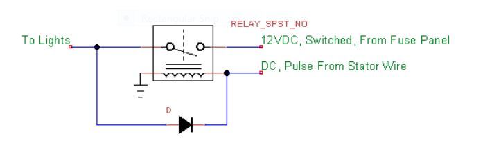
I get your point about the switch, but I just can't let it go. I know, I'm silly but I think the new solution is perfect for my needs. Yesterday I simply tried simply jumping the blue and white wires and it worked like a charm. Although I didn't put a diode into the jumper like you show, which is probably a good idea but I don't have a spare at the moment. I'm kind of thinking that diode is a unnecessary precaution though and I didn't have any problems tinkering with it last night.

So that Issue is finally solved. YES, you can use a standard 4 pin relay for the headlight with only a slight modification. Total cost:

1 x $6 4-pin universal relay (found at any parts store)
1 x Free piece of spare wire about 3" long
1 x $1.50 diode (1N4001), Optional

TOTAL: $7.50 and about 10 minutes of labor.

Alternatively, I'm sure you could also just find a universal latching relay if you wanted.

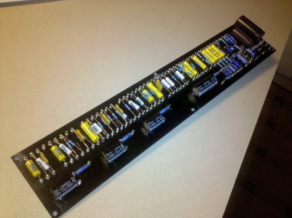
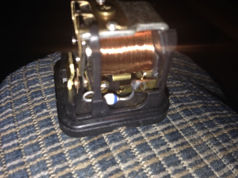
I will post a picture of my set-up when I get home from work.

A big THANK YOU to Arfstrom and Wolfe_11B for taking a large amount of time with my issues. It would appear my charging system works and I was able to fix the PO's headlight mistake. Another thing checked off the list. Now back to those stupid carbs...
 
I am glad this disturbance is almost behind us, I find your lack of faith, disturbing :laugh:


:rock:

Sorry, it just seems I got you going with the "sensing" so I have been a star wars kick, because of it
 
Glad you got it working! The diode is on that relay to prevent the voltage from the stator wire getting to the 12v line. I'd throw one on your jumper wire to be safe, as I think that stator voltage may get a bit high for the lights.
 
Last edited:
Hey rugby, art. Sorry to wake sleeping dogs, did you ever end up getting your charging system to work? I have the same issue with my charging system and headlights.
 
Back
Top