1981 SH Rectifier/regulator + regulator

Richmond

XS400 Enthusiast
Messages
74
Reaction score
0
Points
6
Location
La Jolla, CA
I have a 1981 XS 400 that I am almost done with but one of the last things to do was the wiring. I got a really small battery and converted it to kick start only, and it has worked great. Recently however, there has been shorts and things grounding out in my unused rats-nest of wires in the front of the bike so I took out the stock wiring harness.
I looked at this page
View attachment 3857
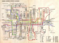
and it appears to be the same set-up as my 81.
As I understand it, the three white wires coming off of the stator are the main power source. These white wires go to the rectifier, and come out in positive (+) and negative (-). Then do they go to a regulator or does that rectifier do both? As the diagram shows it, it seems like then it goes to the battery. Does that current need to somehow pass through the regulator? and why are there separate wires coming off of the stator? are those for gauge lights/ indicator lights?

Happy Thanksgiving!!!
I am thankful for all of the rad advice I've gotten on this forum!
 
The rectifier combines the alternating current from the white wires to direct current (more or less, good enough for our needs...). The voltage regulator reads the output voltage and adjusts the field current (input) of the alternator to control the voltage output to ~14.5 volts. You need both devices and their functions.

You can get rectifier/regulators that perform both functions in one package. There are threads here that detail the conversion, so I won't duplicate that info. It is easier than most people make it out to be, just take your time and you will be fine! ;)
 
So now my next question is; where does the brown line get constant power? From this diagram it looks like brown is the constant power source throughout the bike, and it comes from the stator brushes. The brown wire goes into the regulator, and i assume the green wire comes out with the regulated power and goes to the field coil exciter, the comes out black, and then connects to the brown circuit again. So where does the power in the brown circuit come from? If it is from the brushes, then what gives the stator the power it initially needs?
 

Attachments

  • diagram markup.jpg
    diagram markup.jpg
    218.5 KB · Views: 671
The Brown wire is switched power from the ignition switch.

Start from the battery positive terminal and follow the power (Red wire) as it goes to the main fuse and then to the ignition switch. When the ignition switch is on, it then feeds power to Brown and Blue (L).
 
So now my next question is; looks like brown is the constant power source throughout the bike, and it comes from the stator brushes. The brown wire goes into the regulator, and i assume the green wire comes out with the regulated power and goes to the field coil exciter,

I am going to say you have it backwards. The green / black just turns on the the magnet (aka field coil). so until the right conditions are met, i.e. Key on, main switch on, power energized to just the battery, those two switches, are waiting for you to push the power start button, or kick start it. nothing else is happening, okay, except you can turn on your brake lights, turn signals. If you do kick start, and it doesn't run, the head light is on, cause you have excited the headlight relay, (which is marked relay on the diagram) You can tell its the headlight relay cause it has a white wire running towards it from the stator.

I am sure you have seen the threads where someone is trying to energize the coil so they can do the feeler gauge slap? that is all they are doing is exciting the field coil which will attract your feelers.

Like dave said, follow the power, so after the bike is running, the Brown wire is just monitoring the power from the rest of the brown wire circuit. maintaining the energy level. which is why its tied into the brown wire circuit.

Black=negative\ground, and Brown wire senses a energy expended, (you engaging your brakes turn signals, and slowing down the RPM's as you coast to a stop) Brown wire registers a power need (Voltage Regulator), the green wire energizes magnets then the White wires receive more energy from the electrified magnets, and the rectifier does its job of providing power via the red wire to the fuses, then it goes to the ignition switch, and then to the brown line. So the Rectifier is a series of diodes, that prevents the energy current of going both ways, (AC to DC) White wires are AC, after rectifier power is DC, (notice the white wire going to the headlight, it still has a diode but its is providing extra power for the headlights, till the relay gets the power, it keeps the headlight off saving electricity for the electric start system/kick system (needs over 11.2 or so for successful engine start. Like dave said, I am the guy that loves to expand on things :doh: There is another thread that I read over and over with the same title (rectifier/regulator)

Man I should have been reading the APA instead of this... (my college class reading :banghead: Night guys! (I think I got it right this time!)
 
Ah thank you so much! makes tonss more sense now!! One more question... do wires coming from the stator have to come go into the rectifier with one specific white wire?
 
It is AC (alternating current) at this point. Yes it has to go to a DC making device. I.e. a diode device. DC direct current).
 
Back
Top