How to test the charging system?

Alright my i ask again how to bypass the regulator. Iv'e seen mixed answers. My VR has a black brown and green wire. It is also a solid state regulator. My manual only tells me how to test a mechanical reglator.
 
Last edited:
http://www.xs400.com/forum/showpost.php?p=78311&postcount=59

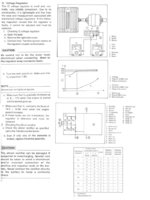
Green wire goes to the Field coil.
Brown wire goes to the the Black wire on the field coil. Which also appears to ingition switch. So I am assuming that the power comes down the Brown wire after the switch is keyed on, and the other on/off/off switch is in the on position,

Lets think if you jumped br to green, The coil would be on at once. How much juice would use? Could it drain the battery over night, just cause you turned off the key, but left the on/off/off switch on?

Normal operation is in conjunction of the rectifier. If the rectifier has more power than is needed it wants to de-energize the field coil. If Power goes below 12 volts, Coil on, over 13.5 (give or take) coil off. Headlight high beam using 65 watts, a hit to the system, so coil on. Oh yea the rectifier also cleans the energy from a 3 stage generator to a DC compatible system. So if that what you wanna do. I suspect that the always on field coil will burn out a subsystem. perhaps rectifier, perhaps your battery will boil away.

Wow, keep us informed, perhaps nothing will happen immediately, for troubleshooting, I seem to remember doing a jumper for something. I am sure I did the energize the green wire, its just been 2 years, so I dont' remember as well as you younger kids might! :D
Good luck!

The black wire is just a ground. It connects up to the rest of the ground circuit. (on the VR)
 
Alright my i ask again how to bypass the regulator. Iv'e seen mixed answers. My VR has a black brown and green wire. It is also a solid state regulator. My manual only tells me how to test a mechanical reglator.
I would imagine that your solid state regulator is similar to, if not the same as, the VR from the DOHC 400 (we can dream).

In the service manual for the DOHC, there is a procedure outlined for testing the VR to determine if it needs replacing. Not sure if by-passing per se is part of the procedure, but if it's wired the same it might help (section 6, pgs 13-16).
 
Hmm, Here it is, in its entiretity, with out the other languages, to baffle us. (Page 6-13 and on.)

I have to think that the normal VR's are simular, as far as Green wire, Br, Bl. This could be used for other trouble shooting,
 

Attachments

  • VR_from the 82 DOHC Manual.jpg
    VR_from the 82 DOHC Manual.jpg
    170.3 KB · Views: 254
Alright so here is an update. I checked the rectifier just because i knew exactly how to. Each diode had the right continuity. So that leaves me with either a bad connection or a bad VR. Now Anyway i followed the procedure for testing a mechanical regulator in my printed manual. I was only able to do one test. The resistance between green and brown leads should be 140ohm replace if more than 10 off. Well my meter reads nothing at 200ohm nothing at 2000ohm and 4.05 ohm. Im not experienced with voltmeters but i believe that would be around 80 thousand ohm? Anyway i believe this may be the problem. Im off to oriley's to pick up a unit i saw in one of drewcifiers old threads. r292 i believe is the code.
 
I'm confused by when it read 4.05... if it read 4.05 in the 20K setting it could mean 80k ohms, but it's been forever since I used a non-auto ranging meter & I can't remember if you have to multiply or if 20K is just the max reading... newer flukes and the like just tell you the exact reading (i.e. it would show "81.0 k").

On a fluke: If by nothing you mean 0 then the resistance is lower that the resolution of the setting . 2000 ohms will read 0 to 2000, but be less accurate if the reading is less than 200 Ohms. If, however, you mean it isn't showing a number (OL, ---, or something) then the resistance is higher than the range can read (an Open if you are at the highest setting).

in anycase it seems like you are way off of 140ohms :shrug:
 
Yes my meter shows a one to the far left when something is out of range. It was showing that 1 in the 200 and 2000 setting. Then it shows the 4.5 in 20k. Either way if its not even registering at 200 then its already waaaaaaaay off. Now this also could be because im testing a solid state regulator and the manual is for a mechanical. Anyway i have a VR being delivered the 17th
 
Put the VR on. Green to green black to black and orange/yellow to brown. No dice. Field coil not magnetizing. Getting 11.5ish volts while running and no change with rmp. I just don't know what to do next. :(
 
I used a ring connector, attached a wire to it, then either plug it in to the normally to the ground black wire, or attach it to the bike. In this pic you can see black wire circling the two wires coming from the VR.
full


This photo you can see it firmly attached to the VR.
full


This photo shows you its attached to the same spot as the ground for the bike.
full
 
Im curious to see how this turns out... I have a 78 sohc and I ended up getting the same 1 ohm readings from the field coil... and with the one resistance test that worked on my (Sold state) voltage regulator I was getting a varying reading that I settled on 180 -190 ohm. The other test to check resistance from black wire to black base of the v reg showed nothing ...... :umm: HEY! maybe I could try a ground jumper for the regulator!!! (im going to look into the variance my cheap meter is adding to the mix... Im not totally convinced my parts are garbage just yet)

It slipped my mind to check if the coil loom is grounding out anywhere. So maybe my working parts are not set up to work properly... or the v reg and possibly stator/loom could still be bad.

would these cause a bike to run poorly... or keep it from running altogether? dumb question I guess the voltage regulator is a pretty key component and a short in either of these areas would get us nowhere fast. Keep us posted
 
fried rotor will toast the RR no matter how many times you replace it, and after the first expensive realization of this, you'll have it working. so do yourself a favor, and ohm out the rotor to see if it's faulty before you install a new RR and fry it too.

So usually, its the rotor and RR, so replace the rotor first, then RR

Here's an AWESOME electrical fault flow chart:
http://www.electrosport.com/technical-resources/library/diagnosis/pdf/fault-finding-diagram.pdf
 
Oh I forgot about this post. It turns out my replacement VR was bad. A new one fixed it. Ill post up an extremely detailed video on testing each part
 
Thank you this is key information. I know it will help me and many others... in turn I guess we can expect to see less questions and more solutions posted.:thumbsup:
 
Back
Top