Milton
XS400 New Member
Hey everyone!
It's been a long time coming for this post. This is my first ever build, so there may be a few cringey rookie mistakes, but that's nothing a little swearing won't fix! After all the help with countless issues on my bike, I felt that it was the right time to upgrade from lurking to an actual post.

The beauty is a 1977 XS400D. I bought it in August 2016 off of craigslist not running (I've been lurking a while...whoops). As I would find out later, it was somewhat neglected and needs some TLC. When I bought the bike, I make sure that it turned over and had compression. At the time, I didn't know about this forum, so diving in reckless to an entire engine rebuild seemed ill advised.
A carb rebuild was the fist order of business, and, with the help of the technical info posted here, I avoided really messing them up. I got lucky that the diaphragms were intact because those things are damn expensive, yikes! The rebuild kit I used was the Keyster Carb Kit for the 400D. Each one runs about $20, but they include a good amount of parts. I went with the shotgun approach to rebuilding the carbs and replaced pretty much anything I could find for a good price. In the end though, I believe that only the main pilot jet would've fixed it..... I don't think the PO knew that running a steel wire through carbs is bad for them, but I'll let the result speak for itself:

If you were wondering, yes that is a giant gouge by the pilot jet, and someone had never hear of JIS heads, because a phillips did a number on the butterfly valve screws. I'm no engineer, but my bet would be that a rough cut into the pilot jet isn't good for laminar flow. Oh well, as long as the bike isn't under 4k, I'll be good to go (fast)! Even with the damage to the carbs, the rebuild kit did the trick and she lived! I took a victory lap around the block with a lot of backfiring and low power, but still power. Once I knew it would run I promptly disassembled her and had to head off to college for the semester.
...3 months later....
After thinking about it for all of fall semester, I was finally able to finally start the full disassembly process in December.


With my luck, the garage was about 0 to 10F ( -15C) that week, so the "warm" glow of those heaters did very little. Oh well, a little frostbite never hurt anyone. Anyway, I made sure to meticulously tag and bag every little piece so I could get it back together next (this) summer.


While taking the baby apart, I noticed that the area under the pivot point for the sway bar had completely rotted out, which is no bueno. While It wasn't a huge issue, with only double shear going to the pivot, I still wanted to ensure that it didn't deform the right side and throw everything in the back off. Going in with the death wheel (angle grinder), I cut out all of the rot and filled it with brand new weld....plus some rebar... whoops. I'm a terrible welder. At this point you're probably thinking: "Wait where did the paint go?" well that adventure is next.


death wheel..Death Wheel..DEath WHeel....DEATH WHEEL!!!
Time came to slice and dice the unneeded parts on the frame for aesthetic purposes. I could feel all of the cringing designers as the grinder make quick work of the end of the frame. After the hacking, all of the old paint, along with the surface rust had to come off. That was a job for the $5 auction sand blaster and some play sand. I will say, sandblasting in December in your front yard in a winter coat gets a few odd looks from the neighbors, probably out of jealousy for the sick xs400 frame! I digress. With the frame and fork all sandblasted they were ready to go off to powder coat. With that, I headed off to university once again.
....another (really long) 3 months later...
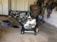
May 2017, time to get serious about knocking the project out! Before anything, I had to step back and admire the shiny powder coat...Must. Not. Get. Distracted. From. Build.....ahhhhh. Ahem, Anyway, I went through and mated the engine back to the frame by tilting both on their side and affixing a few bolts before tilting back right side up (sorry no pictures because my nonexistent muscles were maxed out) Before this, the engine got a good polishing with 200, 400, scotchbrite, superfine steel wool, and some mothers polish, in that order.


The wheels and forks needed to get put on so I could wheel it around the garage that's not mine. With one look at the sprockets, I decided, with the help of the forum, they needed replacement. Apparently shark week isn't as appealing when talking about sprockets, yikes! They were replaced to a ratio of 17-37, from 16-37. I'm a smaller person, so I felt the less torquey ratio could be justified, plus less wear on the engine sprocket. The wheel bearings were also checked, wheels cleaned, and painted. Attaching the fork to the frame was a little more difficult than anticipated with the bike being on a dolly and facing down. The solution was a little, uh, creative, but I figured that 2x4s are a pretty standard shop tool. Yes, I know the handlebars are upside down; I had limited vertical space when it went in storage for the night. The rest of the assembly was pretty standard, no pictures, since it's in the manuals, sorry.


Okay... by standard I meant all of the non modified things, this is where it gets fun and we can break some rules! First on the agenda, the electrical box. The materials costed about $10 here in the US and consist of sheet metal and your choice of paint. I wanted something that would blend into the frame, but still be big enough to hold a powersport battery. It's 2" (+/-5cm) deep, so 4" with the frame and stock seat pan, more on that later. The brackets for the pan mount onto the existing grommet mounts on the frame that were originally meant for the cover. It's secured by the two middle screws. I went with a cheapo battery with 3ah and 50cca, which I found out later barely cuts it. Fair warning: if you have ocd about messy electrical stuff, looking at the last pic may be bad for your health. Finally if anyone starts to worry about toasty electronics and an unwanted seat warmer, it's all good, knock on wood, because the rectifier is mounted under the box. If anyone is interested, I'll be happy to upload the full final designs with dimensions for the box.


Welp, turns out I exceeded the number of attachments for a post, so I'll continue this in part two. Just a little snippet: I'll go over making the stock seat pan into more of a slimmer look, troubleshooting ignition, rererebuilding the carbs, firing her up for the second time, and future plans. If you've made it this far good luck dealing with my B.S. for the rest, because it's all downhill from here!
It's been a long time coming for this post. This is my first ever build, so there may be a few cringey rookie mistakes, but that's nothing a little swearing won't fix! After all the help with countless issues on my bike, I felt that it was the right time to upgrade from lurking to an actual post.
The beauty is a 1977 XS400D. I bought it in August 2016 off of craigslist not running (I've been lurking a while...whoops). As I would find out later, it was somewhat neglected and needs some TLC. When I bought the bike, I make sure that it turned over and had compression. At the time, I didn't know about this forum, so diving in reckless to an entire engine rebuild seemed ill advised.
A carb rebuild was the fist order of business, and, with the help of the technical info posted here, I avoided really messing them up. I got lucky that the diaphragms were intact because those things are damn expensive, yikes! The rebuild kit I used was the Keyster Carb Kit for the 400D. Each one runs about $20, but they include a good amount of parts. I went with the shotgun approach to rebuilding the carbs and replaced pretty much anything I could find for a good price. In the end though, I believe that only the main pilot jet would've fixed it..... I don't think the PO knew that running a steel wire through carbs is bad for them, but I'll let the result speak for itself:
If you were wondering, yes that is a giant gouge by the pilot jet, and someone had never hear of JIS heads, because a phillips did a number on the butterfly valve screws. I'm no engineer, but my bet would be that a rough cut into the pilot jet isn't good for laminar flow. Oh well, as long as the bike isn't under 4k, I'll be good to go (fast)! Even with the damage to the carbs, the rebuild kit did the trick and she lived! I took a victory lap around the block with a lot of backfiring and low power, but still power. Once I knew it would run I promptly disassembled her and had to head off to college for the semester.
...3 months later....
After thinking about it for all of fall semester, I was finally able to finally start the full disassembly process in December.
With my luck, the garage was about 0 to 10F ( -15C) that week, so the "warm" glow of those heaters did very little. Oh well, a little frostbite never hurt anyone. Anyway, I made sure to meticulously tag and bag every little piece so I could get it back together next (this) summer.
While taking the baby apart, I noticed that the area under the pivot point for the sway bar had completely rotted out, which is no bueno. While It wasn't a huge issue, with only double shear going to the pivot, I still wanted to ensure that it didn't deform the right side and throw everything in the back off. Going in with the death wheel (angle grinder), I cut out all of the rot and filled it with brand new weld....plus some rebar... whoops. I'm a terrible welder. At this point you're probably thinking: "Wait where did the paint go?" well that adventure is next.
death wheel..Death Wheel..DEath WHeel....DEATH WHEEL!!!
Time came to slice and dice the unneeded parts on the frame for aesthetic purposes. I could feel all of the cringing designers as the grinder make quick work of the end of the frame. After the hacking, all of the old paint, along with the surface rust had to come off. That was a job for the $5 auction sand blaster and some play sand. I will say, sandblasting in December in your front yard in a winter coat gets a few odd looks from the neighbors, probably out of jealousy for the sick xs400 frame! I digress. With the frame and fork all sandblasted they were ready to go off to powder coat. With that, I headed off to university once again.
....another (really long) 3 months later...
May 2017, time to get serious about knocking the project out! Before anything, I had to step back and admire the shiny powder coat...Must. Not. Get. Distracted. From. Build.....ahhhhh. Ahem, Anyway, I went through and mated the engine back to the frame by tilting both on their side and affixing a few bolts before tilting back right side up (sorry no pictures because my nonexistent muscles were maxed out) Before this, the engine got a good polishing with 200, 400, scotchbrite, superfine steel wool, and some mothers polish, in that order.
The wheels and forks needed to get put on so I could wheel it around the garage that's not mine. With one look at the sprockets, I decided, with the help of the forum, they needed replacement. Apparently shark week isn't as appealing when talking about sprockets, yikes! They were replaced to a ratio of 17-37, from 16-37. I'm a smaller person, so I felt the less torquey ratio could be justified, plus less wear on the engine sprocket. The wheel bearings were also checked, wheels cleaned, and painted. Attaching the fork to the frame was a little more difficult than anticipated with the bike being on a dolly and facing down. The solution was a little, uh, creative, but I figured that 2x4s are a pretty standard shop tool. Yes, I know the handlebars are upside down; I had limited vertical space when it went in storage for the night. The rest of the assembly was pretty standard, no pictures, since it's in the manuals, sorry.
Okay... by standard I meant all of the non modified things, this is where it gets fun and we can break some rules! First on the agenda, the electrical box. The materials costed about $10 here in the US and consist of sheet metal and your choice of paint. I wanted something that would blend into the frame, but still be big enough to hold a powersport battery. It's 2" (+/-5cm) deep, so 4" with the frame and stock seat pan, more on that later. The brackets for the pan mount onto the existing grommet mounts on the frame that were originally meant for the cover. It's secured by the two middle screws. I went with a cheapo battery with 3ah and 50cca, which I found out later barely cuts it. Fair warning: if you have ocd about messy electrical stuff, looking at the last pic may be bad for your health. Finally if anyone starts to worry about toasty electronics and an unwanted seat warmer, it's all good, knock on wood, because the rectifier is mounted under the box. If anyone is interested, I'll be happy to upload the full final designs with dimensions for the box.
Welp, turns out I exceeded the number of attachments for a post, so I'll continue this in part two. Just a little snippet: I'll go over making the stock seat pan into more of a slimmer look, troubleshooting ignition, rererebuilding the carbs, firing her up for the second time, and future plans. If you've made it this far good luck dealing with my B.S. for the rest, because it's all downhill from here!


")


