ThePsuedoMonkey
XS400 Addict
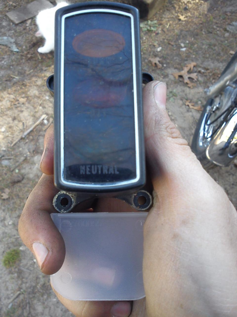
OK, so was browsing around Amazon, ordering tools for my car, when a voltage indicator gauge caught my eye (the same one that I tried to attach to my bike last year). And I thought "yes, I would still like that information about my bike when I'm riding." Nothing I found really got me excited though, especially considering most were going for $40+. Then I started looking into DIY projects... and found only one that was simple and didn't require expensive, hard to find, or complex components. 
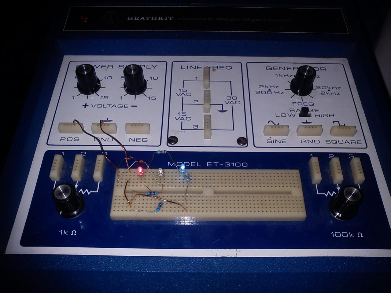
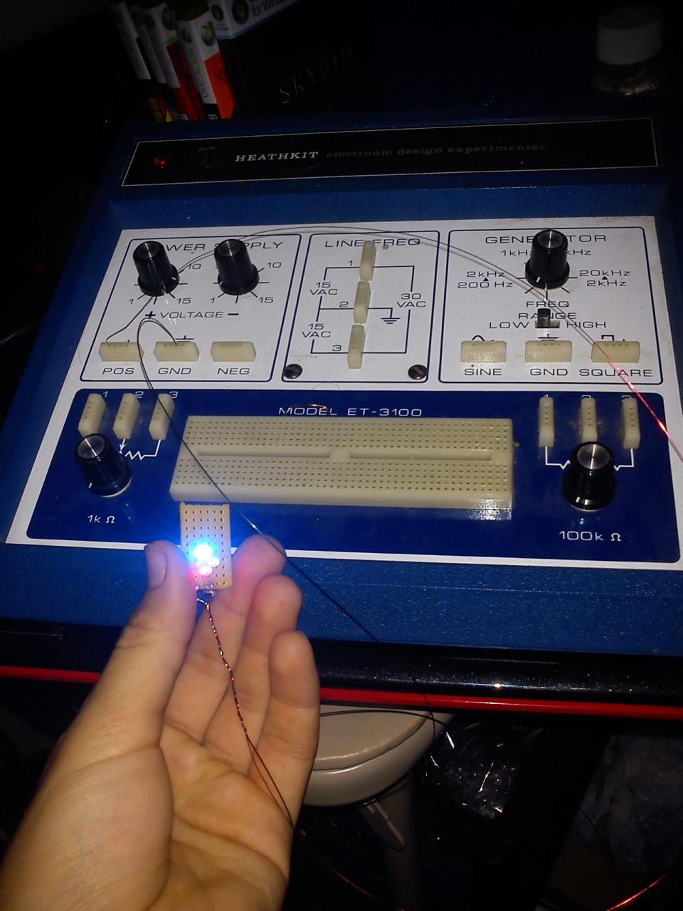
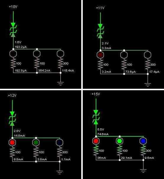
Inspired by that find, I Googled an online circuit simulator and set to work with the specs of typical colored LEDs at my disposal. To me, there were only two acceptable outcomes: an easy to read and highly detailed model based on the number of LEDs illuminated, or a minimalist approach that spans the same voltage range and conveys the important information. I started with the OCD model, but my first attempts were less than impressive, since I was restricting myself to only resistors and LEDs. Retreating to the online radio shack, I picked out one of the zener diodes available and played with that. Eventually I ended up utilizing a little bit of each component to finesse my way toward the minimalist design. At it's most simple level, red=bad green=normal blue=good. It operates between 10V and 15V. The diagram is below, and the actual simulation can be used here.
What you need to know:
-Two zener diodes (Zener Voltage=8.4, Forward Voltage=1.1) in series with the source voltage, and polarity is reversed on the second diode.
-Three different LEDs (Forward Voltage= 2.1, 2.9, 3.1 respectively for red, green, blue) share a node with the zener diodes.
-LEDs are in series with resistors (100, 100, and 300 ohms respectively).
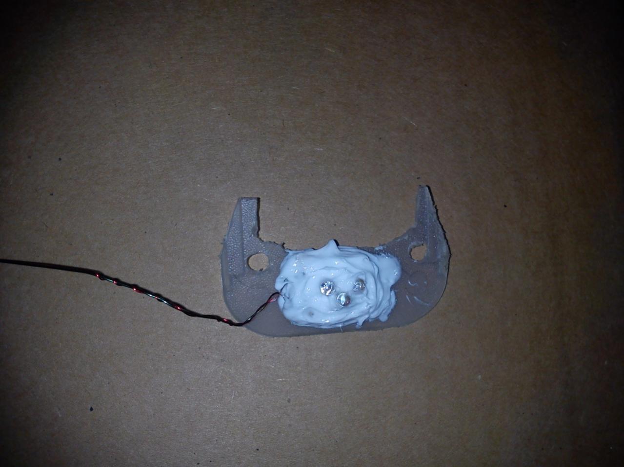
I did my best to make it simple enough for a novice to do in an hour with under $5 worth in materials. Now I just need to think about a tasteful way to mount this!
Inspired by that find, I Googled an online circuit simulator and set to work with the specs of typical colored LEDs at my disposal. To me, there were only two acceptable outcomes: an easy to read and highly detailed model based on the number of LEDs illuminated, or a minimalist approach that spans the same voltage range and conveys the important information. I started with the OCD model, but my first attempts were less than impressive, since I was restricting myself to only resistors and LEDs. Retreating to the online radio shack, I picked out one of the zener diodes available and played with that. Eventually I ended up utilizing a little bit of each component to finesse my way toward the minimalist design. At it's most simple level, red=bad green=normal blue=good. It operates between 10V and 15V. The diagram is below, and the actual simulation can be used here.
What you need to know:
-Two zener diodes (Zener Voltage=8.4, Forward Voltage=1.1) in series with the source voltage, and polarity is reversed on the second diode.
-Three different LEDs (Forward Voltage= 2.1, 2.9, 3.1 respectively for red, green, blue) share a node with the zener diodes.
-LEDs are in series with resistors (100, 100, and 300 ohms respectively).
I did my best to make it simple enough for a novice to do in an hour with under $5 worth in materials. Now I just need to think about a tasteful way to mount this!
 Finally got the set of parts in the mail this week (yay ebay!) so get to finish this simple mod (I call 'em "softmods" now, since they are fairly minor things).