81 XS400SH Cafe

XS-Time

XS400 Addict
Messages
143
Reaction score
0
Points
16
Location
Vancouver Island
Ok time to start a build thread here. I have been working on it for about a year and a half now, maybe longer (i don't like to think about how long it has taken). I will give you the condenced version to get you up to date but if you want all the details you can go here.

http://www.dotheton.com/forum/index.php?topic=14004.0

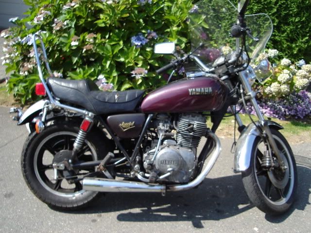
I bought the bike for $500.00 and it seemed like a good deal at he time. But as I got into it I realized that it was only worth $500. Here it is when I picked it up.

2009_0823xs400aug20090002.jpg


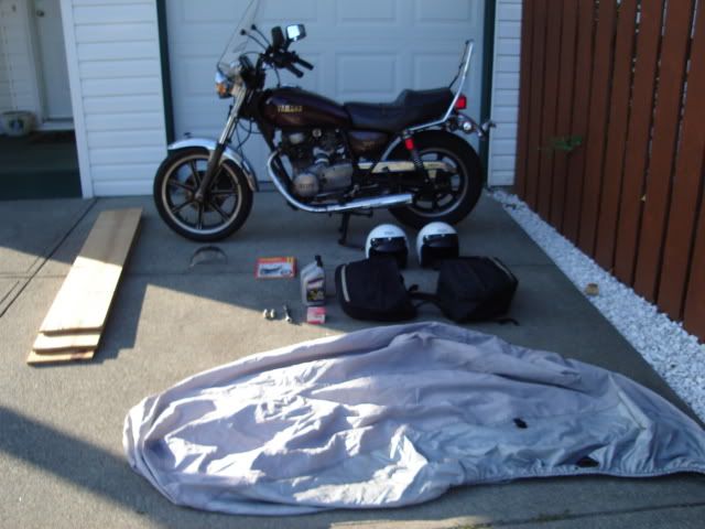
After I paid for it the guy gave me a new bike cover, a couple of helmets and a service manual. Here is all the stuff after I got it home.

Yes he even gave me the wood for ramps and the saddle bags.:thumbsup:

2009_0823xs400aug20090009.jpg
 
The problems showed up when I started to take down the engine. I found bits of metal and this problem inside.

crankcase001.jpg


I've seen a couple of other engines with this problem but i'm still not sure if this is a weakness of this engine or if it is from the kickstart shaft being installed incorrectly.

Anyway I eventually bought another engine and have torn it down and painted it and am getting ready to reasemble it with new bearings. I also bought a XS750 tank and am in the process of mounting it right now.
 
interesting thread, its common for the kicker rear to go because of ham fisted/over-enthusiatic riders just stabbing on the licker instead of engaging the gear first and swinging.
read the other thread and look forward to more of this build
 
Ya I don't think thats so much a weakness like drewpy said.

Its something you could repair. I beleive some of the side covers are magnesium but the crankcase should be aluminum. Have it welded and drill and pin or drill and tap to add strength.
 
Yeah I thought about trying to repair the case but there were other issues with metal shavings in the case and signs that the last guy who took the engine apart was a complete idiot. I did eventualy buy another engine for $200.00 so i'll just keep this one for spare parts. Actually having two motors apart gave me a good idea of what is considered normal for this engine. I had thought that the roller bearings on the transmision shafts in the first engine had spun but after taking the second motor apart I see that the marks in the case are normal.
I get the impression that these motors are pretty durable and that not much goes wrong with them, keeping in mind that they are 30+ years old now. A little maintenance goes a long way. I do recall reading a couple posts where the kickstart lever would only go 1/2 way down and the problem was traced to a kickstart shaft that was installed wrong. I could see how someone trying to force it down could crack the case. It sounds possible but I havent checked it out myself.
 
I reread my first post and it dosen't do justice to the work that I have done so far. I have several boxes of parts to put on and my second motor is cleaned,painted and waiting for me to put it back together with new bearings. I have cut off the rear frame rails and have a couple of other parts made and waiting for there turn to be installed.

Here are a couple of tools that I am using.
Take one cheap polishing kit.....
xs400Feb2011029.jpg


.....add a workbench and 1/2 drill....
100_0318.jpg


..... and you have a bench polisher :wink2:


Then theres my shock compresion tool.
YamMay2011056.jpg


My Dad made this thing in the early sixtys. It's pretty simple. Just several pices of flat bar and some plate steel with a large hole cut in the center.
YamMay2011057.jpg


I still had to hold the head of the top shock mount in a vice to loosen the lock nut. It would have been easier if i had a second pair of hands but I eventually got it.

YamMay2011060.jpg
 
Then I decided to drill some holes in my final drive cover. I didn't want to drill through the webbing so I made this tool to mark the outside.

xs400Feb2011011.jpg


Marked out

xs400Feb2011006.jpg
 
And drilled.

xs400Feb2011026.jpg


Oh and Liam I am planing on a write up on mounting a XS750 tank as it's not as simple as people make it sound. I haven't finished mounting it yet so it will have to wait till later.
 
This is a good time to show what my insparation is. I love classic bikes....a lot. This is what I think of when hear "Cafe Racer".

Norton-1957-Manx-350-11.jpg


Mmmmmm......Norton Manx :bike:

There are a few ideas I have gotten from this bike that hopfully will make it to my bike.

I have to admit that for a while I was worried that my bike might be a bit too small for me. Not in displacement but in overall size. Then one day I came across this picture of a Triton in one of my old classic bike magazines.

Triton001.jpg


Theres something about the bike in this picture that just looks right. Low lean and purposful. No fat ,no extras, just whats needed to go fast.
So this should give you an idea of what direction I am leaning toward with my build. I know ...lofty goals but hopefully it will work out.


My progress has been fairly slow so far and is a bit fustrating but I don't make it easy for myself. A perfect example is my headlamp brackets. When I first started I was going to use these.

45366133751.jpg


There universal (which is good with 33mm forks), cheap and I think they look good. Problem solved....move on to the next task. Then I came accross these brackets on another build.

5863901.jpg


They come from Motolana and are solid stainless steel round stock, welded and polished. I love these brackets but they are around $100.00 which is to much for me.
Still I couldn't stop thinking about them. Then one day I was looking at pictures of vintage bikes in one of my books and I noticed that the bikes with girder front forks used simular brackets but were made from round tubing with the ends squished flat. This reminded me of the stainless steel camper mirrors used on GM and Ford trucks in the 70's and 80's.
 
So I went to my local auto wreakers to look for some mirrors and no luck. I couldn't even find any stainless tubing at the local welders. Then one day I came accross some aluminum tubing at Home Depot.
 
that triton is/was Rick P from Classic bike, great builder but scottish :)
what he can't do with a lathe!
 
Yes it does my heart good to see so many compitent people keeping those old bikes alive. For obvious reasons you have a much more vibrant classic bike community in England than we do here. I know the bikes are here but they all seem like they are hidden away.
 
How To Make BSA Gold Star Style Headlamp Brackets
#################################

First a few cautions:
1- I did this by the seat of my pants and it just happend to work out. It will be easier if you plan it out so I will show you where I would do things different next time.

2- Wear a mask when sanding or polishing aluminum. It has known long term health effects such as Alzhimers.

3-Dont' polish the aluminum unless you like spending time polishing your bike a couple times a year. The aluminum will tarnish and scratch. Painting over the anodizing is a good option. Or better yet find thin walled stailness tubing.

4- Aluminum dents and scratches easly so don't drop it and always use a set of soft jaws (or blocks of wood) in the vice.

This started with this tubing I found at Home Depot.It was around $10.00 so not a bad price for a set of headlamp brackets.

June2011028.jpg


And this picture of BSA Gold Star brakets.

image9.jpg


First thing is to sand off the silver anodizing on the outside.I used a palm sander and I think 320g sand paper. You want to take off the coating but you don't want to scratch too deeply into the aluminum. Even with the palm sander it took me over an hour to sand it all off. It's best to do it now rather than wait till it is bent, as it will be next to impossible to get into the nooks and bends. Be paitient the coating is super hard.
After it was sanded off i gave it a once over with some 500g paper then took it to my polisher.

June2011040.jpg


It came out pretty good. It will get scratched while you make the brakets but you just have to give it a final polish when you are done. You can see my first test "squish" of the pipe. I just clamped it in my small 4" vice without any soft jaws to see how it would come out.

June2011029.jpg


It might come out better with a larger vice but as I had acess to a hydraulic press at work, I used that for the rest of the project.
 
Next is bending the tube into a "U".
Tape one end closed with duct tape and fill the inside of the tube with dry sand. Stop every once and awhile and tap it down with a small stick till it is full. I filled it up then shook it down and it dropped about 1/8" below the top. Filled it back to the top then shake it down. Repeat several times till it wont settle any more. Now tape the end shut. The sand will keep the tubing from kinking like exhaust pipe when you bend it.

Next is making the jig to bend the tube around. There is some good info on tube bending on the net and is worth a read. The short version is that you need a round surface that is actually smaller than the shape you want, as the tube "bounces" back from the shape it was bent into. There is a formula somewhere for this but I don't know what it is.
Knowing this , I decided to ignore it (for some reason) and cut the jig to the size I wanted it to be. I used my headlamp bucket as a guide and drew it out on a pice of 2X6.

June2011034.jpg


June2011038.jpg
 
I used a jigsaw with a guide attached to a finnishing nail at the center of the curve. I'm not sure how but it ended up 1/2" smaller that what I had drawn.
June2011039.jpg


This turned out to be a good thing as the final U bracket was the correct size. You should also keep in mind that the distance between the ends of the bracket will increase when you squish them. You need to adjust the curve of the jig or use spacers like I did.

I then clamped the tube between the jig and a post on my deck (I was replacing my deck) and bent the tube.
June2011044.jpg


It bent easly with nothing more than a good firm grip. There is a small kink in the tube but even I have a hard time finding it. You will notice that the side I started on has a tighter curve than the other side. This is the reason the jig is supposed to be smaller than the actual curve you want. If I were to do it again I would clamp it in the middle of the curve and bend each side down seaparatly.
 
Yes I had a piece of pipe over the end to help bend it but it was not necessary.
I was not sure where the ends would be so I left a lot of tubing on either end of the curve. Unfortunatly this left me with bearly enough tubing for my top brackets. I would suggest measuring better thn i did.
When I decided how long they should be I cut the excess off with a plumbers tubing cutter. I wraped the ends with masking tape and marked where I wanted the holes drilled. I placed the ends between two steel plates with a half circle cut out of them and used a hydraulic press to squish the ends together. I drilled the holes in the bracket as well as making the hole in the headlamp bushings larger.
Nov2011013.jpg


I had to make a longer bolt for my turn signals. It was a funny pitch 10mm bolt that I had to drill the center out of to mount the brackets to the headlamp shell.
 
In the last picture you can see the spacers I made by using a holesaw to drill out slugs from a sheet of 1/4" aluminum. They were then filed, sanded and polished.

Next are the two P brakets that will mount to the two threaded holes in the center of my lower tripple tree. I polished two thin strips of aluminum and drilled the correct size hole to mount them. I then marked where to put a 90 Deg. bend, keeping in mind that there had to be enough room for the bolt head but not so much room that the bracket would bend easly.

Nov2011004.jpg


After bending 90 Deg.
Nov2011005.jpg


I made a jig for the brakets. This also needs to be smaller than the tubing so it will grip well.

Nov2011006.jpg


Nov2011007.jpg


Nov2011008.jpg


Do NOT drill the back hole until the clamp is around the tubing. Then mark the back of the P bracket and remove from the U tubing, then drill.

Nov2011011.jpg
 
Next I designed my guage brackets. You need to know where the guages, speedo and tach cables are before you can plan the top headlamp brackets.
The guage bracket was layed out on paper then transfered to a sheet of 1/4" aluminum. The holes were drilled and I cut the rough shape with a band saw. Finally it was hand filed into shape and polished.
XS400Dec2011036.jpg


The top headlamp brakets or spars were a bit more difficult to make. I took what was left of my tubing and cut it in half so I had two equal spars. Then after filling with sand and taping the ends I put a random bend in each spar. What I should have done was put a bend in the center of the tubing before cutting it in half as it was difficult to bend the two small spars seaparatly. Empty the sand from the spars as i hope you did on the main U bracket.
Put masking tape on the ends of the spars to protect them from damage while squishing them (same goes for the main bracket) as well as giving you a place to mark where to squish and drill holes. I did not squish a long enough area on my upper brackets and had a problem whith them contacting the headlamp shell. I also learned that it was impossible to resquish them longer. The spar just pushed out of the plates I was using. If you have enough tubing you can make large squished ends to allow you to adjust the fit of the spar. The ends can be trimmed off later.
My plan was to mount the spars to the same bolt as my guage bracket but that put the spar in the same place as my speedo cable so I had to use the threaded holes that the ignition lock was attached to (I guess i'm relocating my ignition switch).
You can bend the end of the squished area to adjust the spars to fit properly. As it was I had to make spacers to drop the spars down to clear some of the bolts on my guages.
 
The spars were drilled and test fitted to the headlamp. This is when I realized that the right spar coverd part of the hole drilled for my indicator lights. As I had no more tubing and was to cheap to but more I wrapped the spar in masking tape and marked where the lamp would contact it.
I strapped the spar to a pice of wood so it would not bend and placed some roundstock aginst the area the lamp would touch. I used the hydraulic press to push a grove into the side of the spar. I had to do this again to less of an extent to clear the tach cable.
Then a test fit.
Nov2011025.jpg


Nov2011032.jpg
 
Back
Top