Resistance readings

Campbell45

Penny Pincher
Messages
93
Reaction score
0
Points
6
Location
Indiana
So I'm hunting down my charging issue right now. I'm testing the resistance on my stator and field winding and this is what I get

Stator between the three: 1.0-1.4 ohms

Field winding: 5.6 ohms

I know the book wants you to have:

Stator: .72 ohms

Field winding: 4 ohms


Is this okay? My stator windings are probably high because the insulation is broken showing the wires. I plan to rewire them but should I be worried about needing to replace anything?

btw drewpy if your reading this nice tip for renewing the stator wires in your how-to :thumbsup:
 
So I checked out my wiring and its all good and wired correctly. Guess I'll just replace my regulator and rectifier and hope for the best
 
Is it not charging or have you just decided to test the ohms? the readings fluctuate with temperature so they may not be that much out.
 
I believe I found the problem. With the key on is the regulator supposed to power the field coil? or is it only when the bike is running?

With the key on my regulator does not power the field coil. I have yet to test it with the bike running..
 
looking at the wiring diagram, the ignition supplies direct to the field coil via Brown and the regulator supplies the earth via green wire.
 
I'm watching this too because I have the same issue and I just rewired the stator. I get 1.8 ohms resistance on my stator leads (previously zero due to oil soaked, frayed destroyed wiring: photos to come), and 5.2 on my field coil. I cannot see a climb in voltage with engine revved and I am suspicious there's a short to ground on the coil or on the stator, both would be very hard to find. However, I am going to find it! It's my obsession.

Is there a way to remove the stator and field coil and rotor and test them outside the bike where shorts would not occur?
 
looking at the wiring diagram, the ignition supplies direct to the field coil via Brown and the regulator supplies the earth via green wire.


So as soon as your turn on the ignition but not running the regulator should provide the ground since its not seeing 14.5 volts, correct?

My regulator is not providing the ground, thus not exciting the field winding.

I believe my only option is to replace the regulator. 5 ohms of resistance would still let the field winding be powered..


Drewcifier- I may be wrong but isnt the regulator you have meant for the xs650? I cant seem to find a clear answer on which aftermarket regulator we can use thats commonly found at an auto parts store. I may just buy one from electrexworld
 
So as soon as your turn on the ignition but not running the regulator should provide the ground since its not seeing 14.5 volts, correct?
I think that's right, from what I've seen these regulators do not restrict the charging system until they are triggered. Unless the regulator fails it won't trigger until it gets over 14V. Usually you can rule out problems with them by bypassing it entirely, and then checking for changes in the system.
Is there a way to remove the stator and field coil and rotor and test them outside the bike where shorts would not occur?
Easy enough: remove the covers on the left side of the crankcase (the leads from the windings are hidden under the sprocket cover). The rotor is just a hunk of metal, while the stator is mounted to that side cover, with the field coil coaxial with it so that it fits inside the rotor. If anything, I'd suspect any damage to be at the rubber grommet.
full


Darn electrical gremlins :guns:
 
Guess I'll bypass the regulator and see what happens. To bypass is would I have to remove the regulator and hook up one of the field winding wires direct to the battery and then ground the other?

After that depending on what I find I'll give the r292 a shot
 
Found the problem!

I was feeding power to the brown wire going into the regulator. (which I think is correct?) and getting nothing back from the green.

I switched the power between brown and green. (so feeding green) and got power out of brown.

So this means it should power the field winding. I'm gonna throw it all together tonight and see what I get.

Unless my wiring was wrong to begin with isnt this odd? I thought green was ground?
 
Well, we shall see. Keep us posted. I'm very curious if the link from pamcopete had me wire mine up wrong. As I was told to power the orange/yellow combined wire off the aftermarket with the brown from the bike and then send green to green and black to black.
 
If the swapped wires help, let me know asap.

I'm still clarifying how this system works. Anyone can chime in to correct my theory. I still need help in fixing my charging system so I'm trying to understand the concept first.

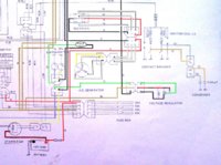
Charging theory: Think of the charging system as an external system powered by the green wire to the field coil. Once powered, the coil creates an excited field which is broken by the spinning rotor, creating ac waves in 3 phases. These are the three white wires that leave the stator, and go to the connection with the rectifier as AC.

The rectifier removes the downward or negative dip in the sine wave by reversing current, preserving only the peaks of the upward positive part of the wave. The wave keeps swapping into positive mode, never going negative. The output amount is a lot, as I understand it. Somewhere around 50 volts acv.

The current produced now needs to be regulated. (Someone correct me if I'm wrong in the following description.)

The rectifier feeds an output of positive voltage into the brown wire (on my bike it's red/black wire), which goes through the regulator exiting on the green wire. If the voltage on the brown wire (going in) is above a certain amount, a switch closes in the regulator and the voltage then passes through a step down coil that reduces the voltage to a reasonable amount (this is the way the system prevents too much power from going to the coil, and therefor producing too much ac to rectify) So the ever increasing amounts of AC produced by the stator wires never reaches an amount to overheat/boil out your battery.

Riding will now lower the overall voltage in the system. When the overall voltage gets below a certain point, the switch opens again, and the field coil is re-excited, starting the charging process over again.

Given all of this, if the green wire is never fed voltage, ie if you disconnect the green wire going INTO the regulator, then the bike simply operates as a battery powered combustion engine, and has no problems doing so. How do I know? I rode mine 90 miles with connector to the regulator hooked up to nothing, and had zero problems. As long as no power enter the regulator, it can't power the field coil, no ac is generated, no harm, no foul.

So I hope this is the correct theory, and helps you power the right wire, and get the right output to your green wire.
 
Last edited:
Well, we shall see. Keep us posted. I'm very curious if the link from pamcopete had me wire mine up wrong. As I was told to power the orange/yellow combined wire off the aftermarket with the brown from the bike and then send green to green and black to black.

the xs650 has brushes (well the pamcopete bit I read) so I can't see it being the same. Ours are switched earth to the field coil.

I can temp by pass the reg if you earth the green lead and power the brown, then you should see some charging (if the battery is good) don;t do it for too long or the battery will go BOOM!!
 
Drewpy, thanks for checking in, can you clarify what switched earth to the field coil means?

Which wire would SEND power to the field coil? There is a black one and a green one connected to the coil. Is black sending power, and green the return (earth?) This is what Campbell and I both need to know.
 
In standard Jap wiring, black is always ground, remind me which year bike you have (or put it in your sig for ease of reference) then I'll check the yam manual to confirm.

I've seen brown and green wiring from the field coil.
 
I have the 1976 xs 360. My wires to my coil are green and black.

My wires connecting to my three prong at my regulator are black/red (matching the brown position in the testing diagram), green, and black.

Since you're saying green is earthing for the coil, I wondered if I needed to power the black wire...
 
colored wiring diagram from my manual. Coloring in photoshop.

Jpeg of wiring from my manual. Shows a small spiral above the neutral light/oil light connector. Is that my field coil? If so it looks like the brown connects to the red/black wire on the regulator. Please verify. That is where power enters the regulator?
 

Attachments

  • my wiring.jpg
    my wiring.jpg
    173.5 KB · Views: 228
Last edited:
Instead of fooling around with switching wires I bypassed the regulator and had 14.9 volts at the battery while idling.

This proves my regulator is the culprit, ordering one now!
 
Back
Top