Weird, my 81 wasn't wired like that. Does the 82 run off of a different wiring diagram?
-
Enjoy XS400.com? Consider making a donation to help support the site.
XS400.com receives a small share of sales from some links on this page, but direct donations have a much greater impact on keeping this site going.
You are using an out of date browser. It may not display this or other websites correctly.
You should upgrade or use an alternative browser.
You should upgrade or use an alternative browser.
Yet another charging issue...
- Thread starter rugbywarrior89
- Start date
rugbywarrior89
Need more time...
Not really. I mean there are subtle changes to between models but generally they are the same. I'm just making assumptions based on what I've seen.
I know the VR ties to the brown wire and that the positive battery terminal goes to the starter solenoid and the main red (might be red/yellow) wire tees off and goes to the fuse block. I assumed the brown must go to the ignition somehow since it only gets power once the key is on. And like I said before I assume it goes inside my headlight bucket somehow simply because that would piss me off.lol I should post a pic of my headlight bucket. When I opened it up it wa a very
 kind of moment. It was just a giant ball of wires that the PO hacked together. I have since made some sense out of it but its still pretty bad.
I responded to you pretty quickly, I suppose I should have looked at the wiring diagram before I posted to prevent somebody from being very confused later on.
I know the VR ties to the brown wire and that the positive battery terminal goes to the starter solenoid and the main red (might be red/yellow) wire tees off and goes to the fuse block. I assumed the brown must go to the ignition somehow since it only gets power once the key is on. And like I said before I assume it goes inside my headlight bucket somehow simply because that would piss me off.lol I should post a pic of my headlight bucket. When I opened it up it wa a very
kind of moment. It was just a giant ball of wires that the PO hacked together. I have since made some sense out of it but its still pretty bad.I responded to you pretty quickly, I suppose I should have looked at the wiring diagram before I posted to prevent somebody from being very confused later on.
The regulator doesn't go straight to the battery, it ties into the brown wire which then goes to the fuse box, then the ignition (in some roundabout way), back to the fuse box via the red wire, through the starter solenoid, and finally to the battery. So somewhere in this plethera of wiring, there is a bad connection.
Stop it, or we will send you to the corner, Again!
Black wire is going to the harness for ground.
Brown is attached to brown which is also attached to the field coil. So that should be sensing the current level.
Green is to turn on the field coil when the power is insufficient.
Now don't make it harder again, or no more beer.
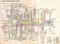
seriously you have found the color wire diagram? (the XS400sh) seems to be very versatile for the 80-82 bikes (SOHC)
Attachments
rugbywarrior89
Need more time...
Well now, I have been schooled again. So the brown wire going to the VR is only a sensing wire. Thats interesting. However the field coil still has to get its (+) charge somewhere and by that color diagram you attached, the power is still supplied to the field coil via the brown wire, just directly and NOT through the VR. That said I still need to probe between the battery (+) and the field coil (+) wire as well as between the battery (-) and the field coil (-).
I will say though that I always solder my grounds so it is probably in the (+) wire somewhere.
I will say though that I always solder my grounds so it is probably in the (+) wire somewhere.
Full rewire. Come on over to my place on a Saturday with $30 of wire and a case of beer. We will get you up and running.
rugbywarrior89
Need more time...
That does sound like a plan but unfortunately, I'm going to be booked solid for the next few weekends. But I will definitely keep that in mind when I do get a chance. I also need to think through a few mods I would like to make in the wiring like maybe a keyless ignition and handlebar buttons inside the handlebars. I figure if I'm gonna do all that work, I may as well do it right the first time. But that also means I will want a new set of handlebars, a bunch of relays (since those types of buttons wouldn't carry that kind of charge) and some other things. You can see why I was wanting to make that a winter project.
I know the keyless ignition is kind of stupid since I still need a key for the gas tank and seat but having my motorcycle automatically light up and be ready for action as I sit down would be sweet.
If anybody knows uf a keyless gas cap, that would be awesome
Edit: I meant one that still locks and works with the keyless ignition. Not just a screw on that people can steal from.
Last edited:
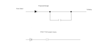
@wolf, that mini diagram is just the bike starter series. Its in that 44meg download supplemental pack for all the bikes. The one where the author starter out by promising to give everyone a copy, then that got overwhelming, so he found a spot to put big files for others to download. And still everyone asks for a file to download, (i had to unsubscribe from that post cause no one read that it was a downloaded file now.)((Stick a fork in me, I am done, people don't read)) I have a shorter one of just the SH model (4R4) compatible with G's. but its 1.5 megs, and I can not upload it here. oh well. I did make a few changes, with explanations, (Yamaha will never pay me for)
Brown / Green I have to believe the brown wire will positively charge the green wire when it senses a brown out, (hahaha) No body understands.
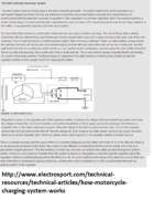
http://www.electrosport.com/technic...articles/how-motorcycle-charging-system-works
Here is the png image of the part that is special to us. There may be better terms young jedi, but even you can sense a change in the force
Brown / Green I have to believe the brown wire will positively charge the green wire when it senses a brown out, (hahaha) No body understands.
http://www.electrosport.com/technic...articles/how-motorcycle-charging-system-works
Here is the png image of the part that is special to us. There may be better terms young jedi, but even you can sense a change in the force
Attachments
rugbywarrior89
Need more time...
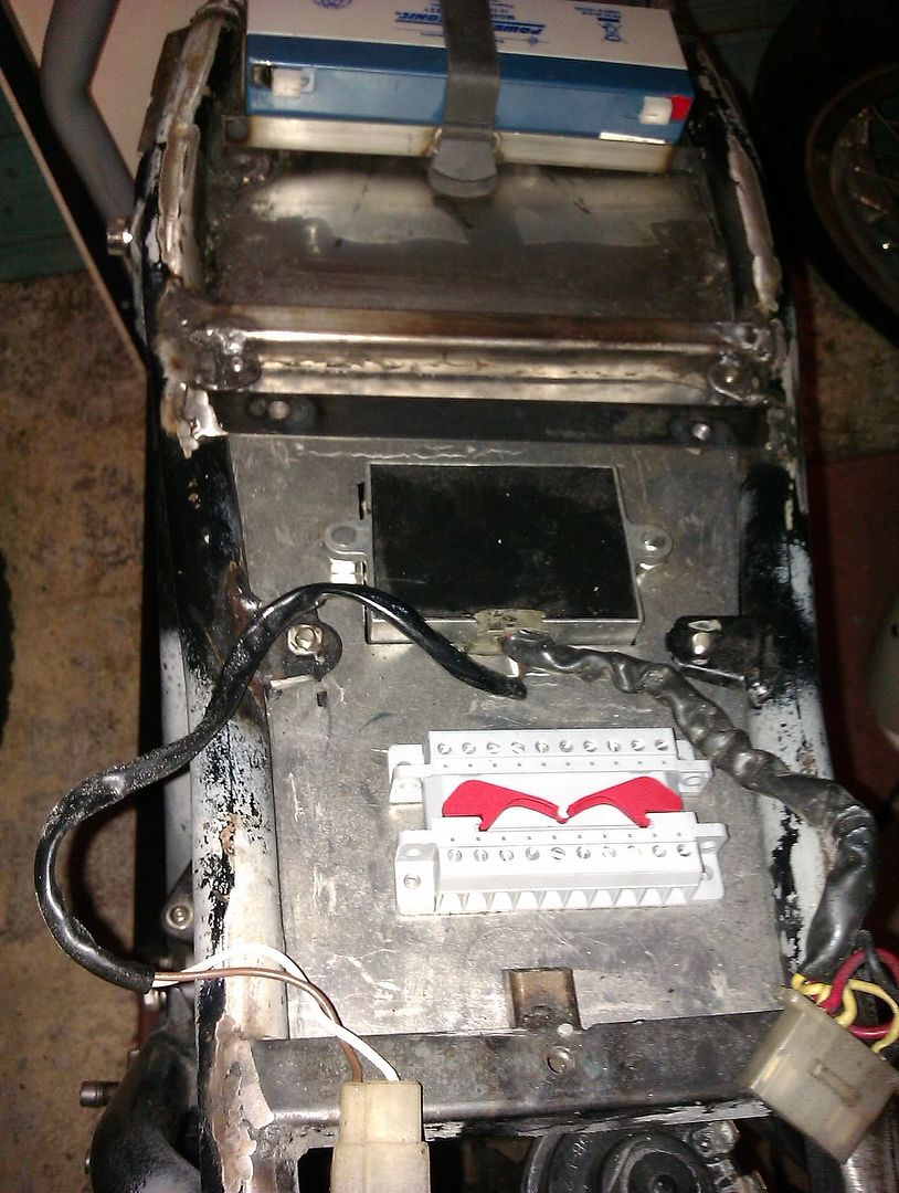
Well, I hooked it all up and figured out some things. For instance, I figured out that I hope I never meet the PO in a dark alley some day
I think my problem could have been this:

Or maybe this:

Or possibly this:

I'm not afraid to solder but lets just say that it's not my favorite past time. Anyways, thats fixed. 13.2 at 2k rpm. Didn't take it to 5k cuz its late and I'm currently bypassing my VR. I need to pick up another VR tomorrow.
@Arfstrom, so I said before that the universal relay worked but the diode wasn't on. When I put the diode on, the relay was buzzing and the headlight was much dimmer and flashing a bit. When I switched the diode around, it didn't work (thats a good thing). When I bypassed the diode like before, the relay worked fine and the headlight was nice and bright. I know that diode is supposed to be there but what the heck is going on?
I think my problem could have been this:
Or maybe this:
Or possibly this:
I'm not afraid to solder but lets just say that it's not my favorite past time. Anyways, thats fixed. 13.2 at 2k rpm. Didn't take it to 5k cuz its late and I'm currently bypassing my VR. I need to pick up another VR tomorrow.
@Arfstrom, so I said before that the universal relay worked but the diode wasn't on. When I put the diode on, the relay was buzzing and the headlight was much dimmer and flashing a bit. When I switched the diode around, it didn't work (thats a good thing). When I bypassed the diode like before, the relay worked fine and the headlight was nice and bright. I know that diode is supposed to be there but what the heck is going on?
I scene something yesterday about the headlight not minding if e energy is AC or DC. I suppose if the PO had isolated the headlight from the rest of the wiring, could be fine. This is thread that started out blowing fuses right? If that is the case all you might need to do is ground out the headlight in the bucket? Ask your maintenance buddy if that sounds right? Both turn signals ground out there. Unless there is a back feed though the turn signals? Idk.
The file I added is for reg rec trouble shooting.
The file I added is for reg rec trouble shooting.
Attachments
rugbywarrior89
Need more time...
I'm not exactly sure how the original relay worked but the new relay I just put on only powers the relay and closes a 12V DC connection to the headlight. The headlight never gets an AC current. But the AC current powering the relay does go to ground. I'm a little concerned because I read a post by Drewpy about AC to ground cauising feedback issues with out charging system.
so what the diode is doing is a form of voltage rectifying (rectifiers have 4 diodes) and this stops the AC pulses from affecting the DC relay and feeding back to the alternator.
I wasn't sure. I remember some had the fuses popping. That's probably it.
rugbywarrior89
Need more time...
I I think I may have figured it out... sort of. I'm not sure why the relay is working with the AC current except that maybe the voltage fluctuates fast enough and the armeture will close with either polarity so the AC will still close the circuit. That still won't stop feedback. When you put a diode on the line, the relay stops seeing the (-) portion of the alternating current and thus only gets voltage half the time causing the aremture to open and close rapidly, hence the buzzing. My guess is that the bronze relay that came stock with the bike has some sort amazing method of being able to provide a constant voltage after the diode.
I'm no electrical engineer so someone please correct me but placing a small capacitor after the diode should store the needed energy and release it to the relay during the (-) portion of the AC phase, thus providing a constant DC current to the relay. Research I found said that rectified AC current should be filtered to prevent ripples voltage (see the last page of the attachment). Would that do the trick?
PDF also found here: https://www.google.com/url?sa=t&rct...=G4OfMpSsMyEoZeOl_Q49OQ&bvm=bv.74115972,d.aWw
Attachments
rugbywarrior89
Need more time...
Does anybody know the current (Amps) of the white headlight wire after the diode? I need to figure out what capacitance I will need.
I assumed 10A and it came out to 35mf which seems REALLY high. The capacitor is also $35 compared to $1.50 that 99% of capacitors are. Something tells me that overkill.
I assumed 10A and it came out to 35mf which seems REALLY high. The capacitor is also $35 compared to $1.50 that 99% of capacitors are. Something tells me that overkill.
rugbywarrior89
Need more time...
While on the subject of wiring, Drewpy's ride has a power distribution box or something. If it is a power distribution box, Where the heck do you find something like that? The only one I have found was like $250.
I on a tablet, so I can't see everything. I found this.
http://www.xs400.com/forum/showpost.php?p=135525&postcount=219
That thread we went on for ever. In there somewhere scrorpy did post a pic of his new one from OEM store. The color banding should tell you everything you need to know. I did spend sometime on a web site called 12volt.com or something like that.
That relay diagram I had found, I was trying to show there isn't always a straight across one, but I suspect your right. Any current will close the magnetic switch. It should also add power to output line, which the generic doesn't do.
rugbywarrior89
Need more time...
I understand what you were saying and I'm not sure if the old bronze relay worked like that or not but I do know how my new relay works. So I guess my question then is this:
Do I even need a diode if the AC current is powering the relay and going straight to ground? If so, will a capacitor stop the relay buzzing and give me full power to the headlight?
PS. I've been waiting all day for you to go to lunch.lol
Posted via Mobile
Do I even need a diode if the AC current is powering the relay and going straight to ground? If so, will a capacitor stop the relay buzzing and give me full power to the headlight?
PS. I've been waiting all day for you to go to lunch.lol
Posted via Mobile
I don't know, scorpy was going to put everything back to stock. The mods I have done, I think you have scene them. Auto vr, combo RR that didn't work. (Vr just happened to die.). When I suspicions of my relays not working, I flopped them around. I got headlight came on. I didn't need the relay ordered. Now that I went though that, I know there is a difference between old and new, I suspect scorpy was going to just use female connectors. http://www.xs400.com/media/albums/345/
rugbywarrior89
Need more time...
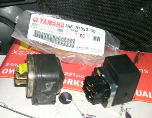
Believe it or not, both of those relays use the same connector.The black plastic goes around the outside of the white plug. I have one of each on the underside of mine (had...sorry).
I could not get the new one to fit, I was befuddled? why would the manafature make soemthing that didn't fit? Where is the converter? (at that time, Why do I need to modify anything? I was lucky, mine oringal worked.
heres that website with info on relays. I am trying to figure that out, instead of reading 33 pages of research. I wonder if they can count?
http://www.the12volt.com/relays/relays.asp
heres that website with info on relays. I am trying to figure that out, instead of reading 33 pages of research. I wonder if they can count?
http://www.the12volt.com/relays/relays.asp
rugbywarrior89
Need more time...
Well I really do suck at electronics. I decided to go for the capacitor and see what happened. I bought the biggest one they had at Radioshack just to be safe. It was 4700uF at 35VDC. Took it home and hooked it up and it didn't work. When I touched it to the wire, the headlight would light up for about 1/2 second then nothing. Flipped it around and it did it again. Not sure whats going on. I wonder if I should run the capacitor parallel with a straight wire. Anybody know?
Attachments
Similar threads
- Replies
- 7
- Views
- 754