-
Enjoy XS400.com? Consider making a donation to help support the site.
XS400.com receives a small share of sales from some links on this page, but direct donations have a much greater impact on keeping this site going.
You are using an out of date browser. It may not display this or other websites correctly.
You should upgrade or use an alternative browser.
You should upgrade or use an alternative browser.
1981 XS400 Scramblerized Build, eventually...
- Thread starter JimVonBaden
- Start date
JimVonBaden
"Cool Aide"
These were provided to me for my bike to help with my wiring diagram.
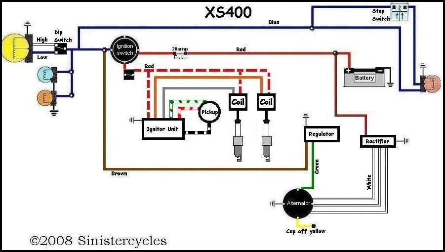
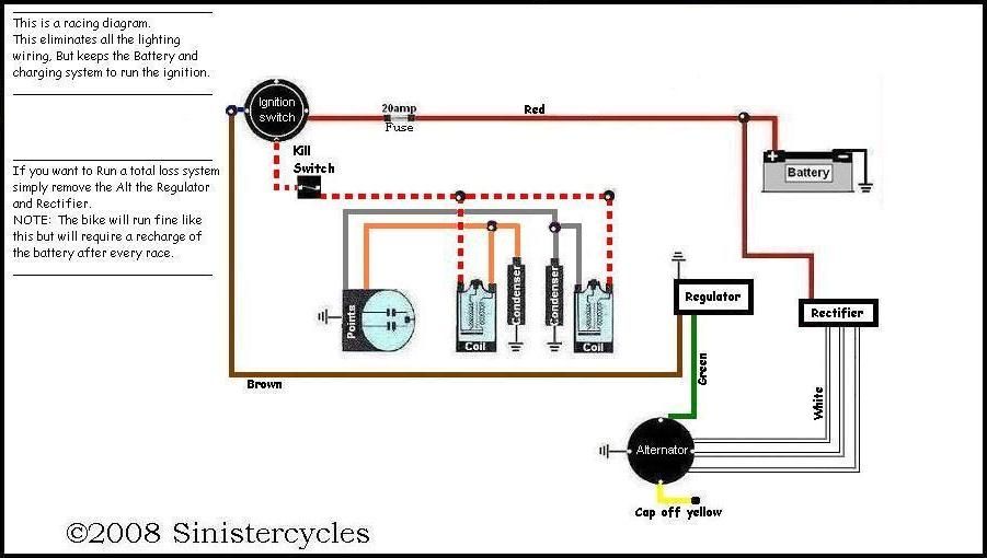
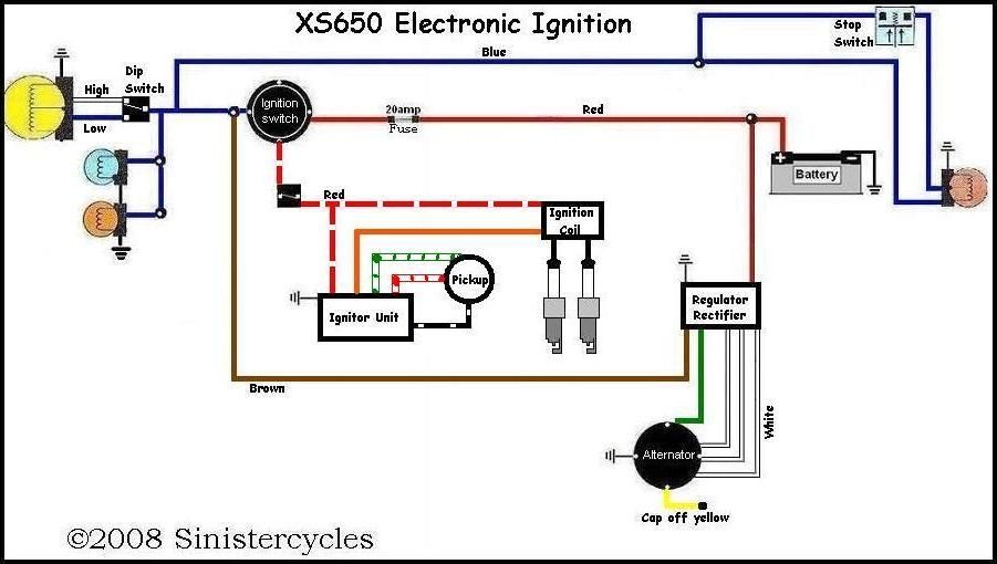
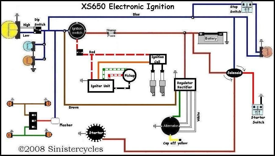
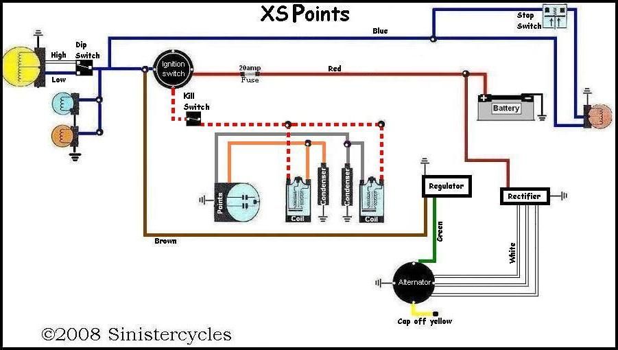
Some are for race bikes with the charging system removed, some with lights and some without lights.
Some are for race bikes with the charging system removed, some with lights and some without lights.
Well, I see a few issues:
A single fuse is asking for trouble - a short in a marker light will shut the bike down.
Only 1 brake light switch. You will need 2, one for each control.
No high beam indicator.
No oil pressure light.
No turn signal indicator lights.
Other than that, it looks rather simple.
A single fuse is asking for trouble - a short in a marker light will shut the bike down.
Only 1 brake light switch. You will need 2, one for each control.
No high beam indicator.
No oil pressure light.
No turn signal indicator lights.
Other than that, it looks rather simple.
JimVonBaden
"Cool Aide"
Well, I see a few issues:
A single fuse is asking for trouble - a short in a marker light will shut the bike down.
Only 1 brake light switch. You will need 2, one for each control.
No high beam indicator.
No oil pressure light.
No turn signal indicator lights.
Other than that, it looks rather simple.
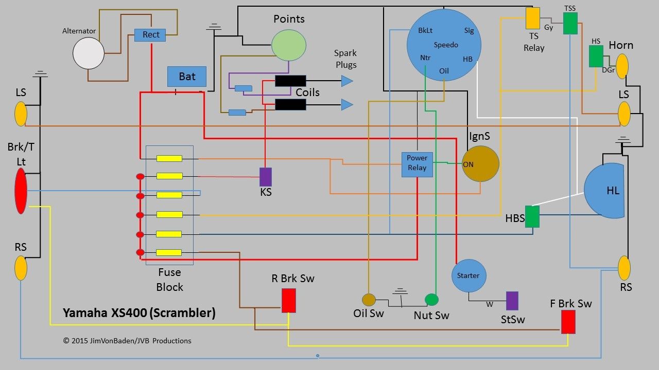
Now critique mine!
I'll take a stab at it. No guarantees.
-Rectifier missing ground.
-Not seeing a voltage regulator?
-Starter and starter switch: starter motor should be between the starter relay and ground.
-Speaking of the starter relay. You don't have one.
-Disconnect battery ground from points ground. Battery gets grounded on its own.
-Wait a minute, points? Doesn't your bike have a TCI?
-If it does have points, you're missing the condenser.
-Why three separate fuses for lights?
-Swap the horn and horn switch locations. Would work either way but generally switches are between the load and ground.
-Turn signal indicator in the speedo isn't hooked up.
-Will you be doing LED flashers? Might want to throw some diodes in to prevent back feeding them.
-What's the deal with the power relay? Stock configuration doesn't use one. Not really necessary unless you reconfigure it somehow to keep the lights off until the motor is running to make starting easier.
-Don't think the ignition switch should be going to ground. If it's the stock switch you'd create a dead short to ground and blow the fuse every time you turn the key.
I have a power relay on my bike as well. It takes the load off the ignition switch and can be replaced or bypassed at the side of the road faster than most could call for a tow truck.
All I can add to BBS360's points is that the output from Rectifier/Regulator (I'm guessing you are using a solid state R/R) should connect to the other side of the fuse. Just in case...
All I can add to BBS360's points is that the output from Rectifier/Regulator (I'm guessing you are using a solid state R/R) should connect to the other side of the fuse. Just in case...
The stock '81 headlight relay taps AC power directly out of the stator.
The stock relay won't work with the current wiring diagram.
The stock relay won't work with the current wiring diagram.
A standard SPST 40A relay is what I'm using. I'd be surprised if Jim was planning anything else based on his diagram. For less than $10, including the harness, it would be silly to reuse 30+ year old stock parts.
JimVonBaden
"Cool Aide"
Thanks everyone, I will look at your comments and rework the diagram.
Correct. The only reused wiring will be around the charging system. Everything else will be new.
A standard SPST 40A relay is what I'm using. I'd be surprised if Jim was planning anything else based on his diagram. For less than $10, including the harness, it would be silly to reuse 30+ year old stock parts.
Correct. The only reused wiring will be around the charging system. Everything else will be new.
That'll work then. Still looks like the power relay will be a dead short to ground when activated.
Might want to combine the lighting under one fuse and feed that fuse through the relay.
Might want to combine the lighting under one fuse and feed that fuse through the relay.
Without detailed labeling of the power relay connections, I'm going to guess that Jim intends the ignition switch to provide power to trigger the relay. Not sure why the ignition switch needs a ground, but that is a separate issue.
I prefer more fuses, so we will have to agree to disagree about that. :^)
I prefer more fuses, so we will have to agree to disagree about that. :^)
Jones
XS400 Enthusiast
Hey. Any chance you want to get rid of the pipes that were on the bike before you made the high pipes? PM me please. Thanks
JimVonBaden
"Cool Aide"
Hey. Any chance you want to get rid of the pipes that were on the bike before you made the high pipes? PM me please. Thanks
Possibly. I don't think I will need them.
JimVonBaden
"Cool Aide"
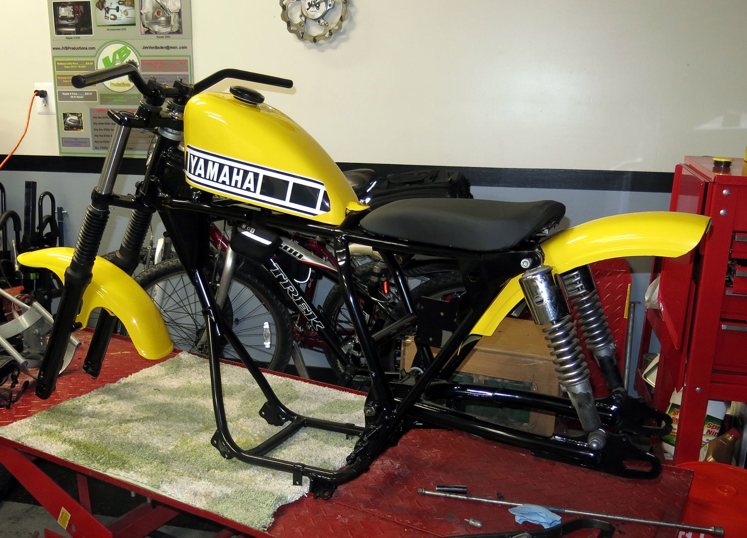
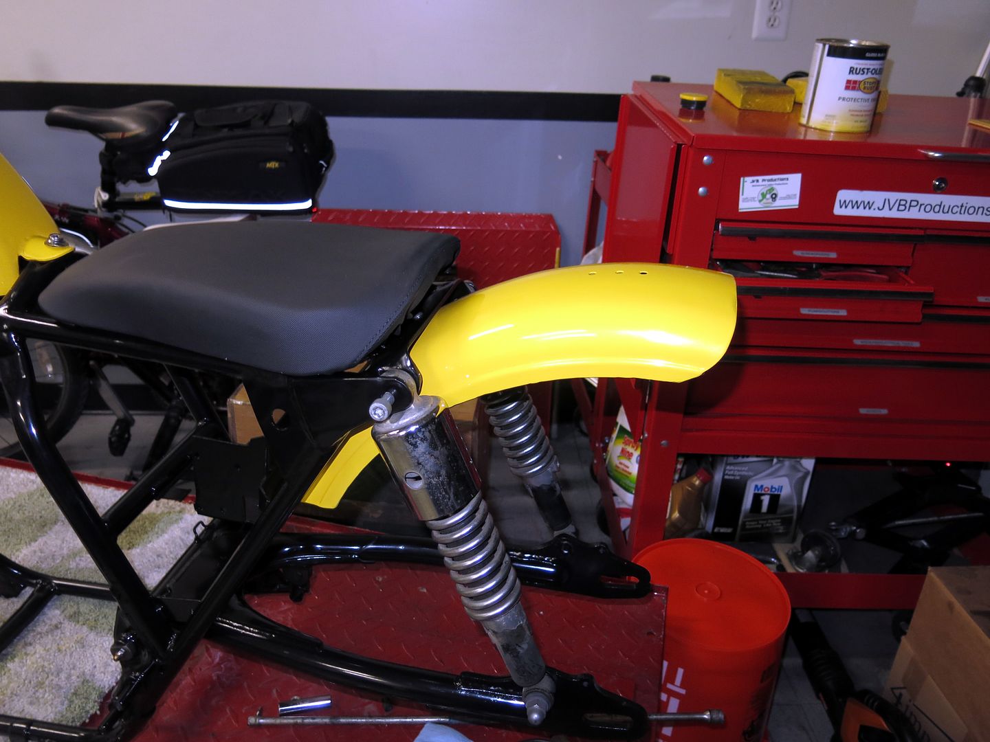
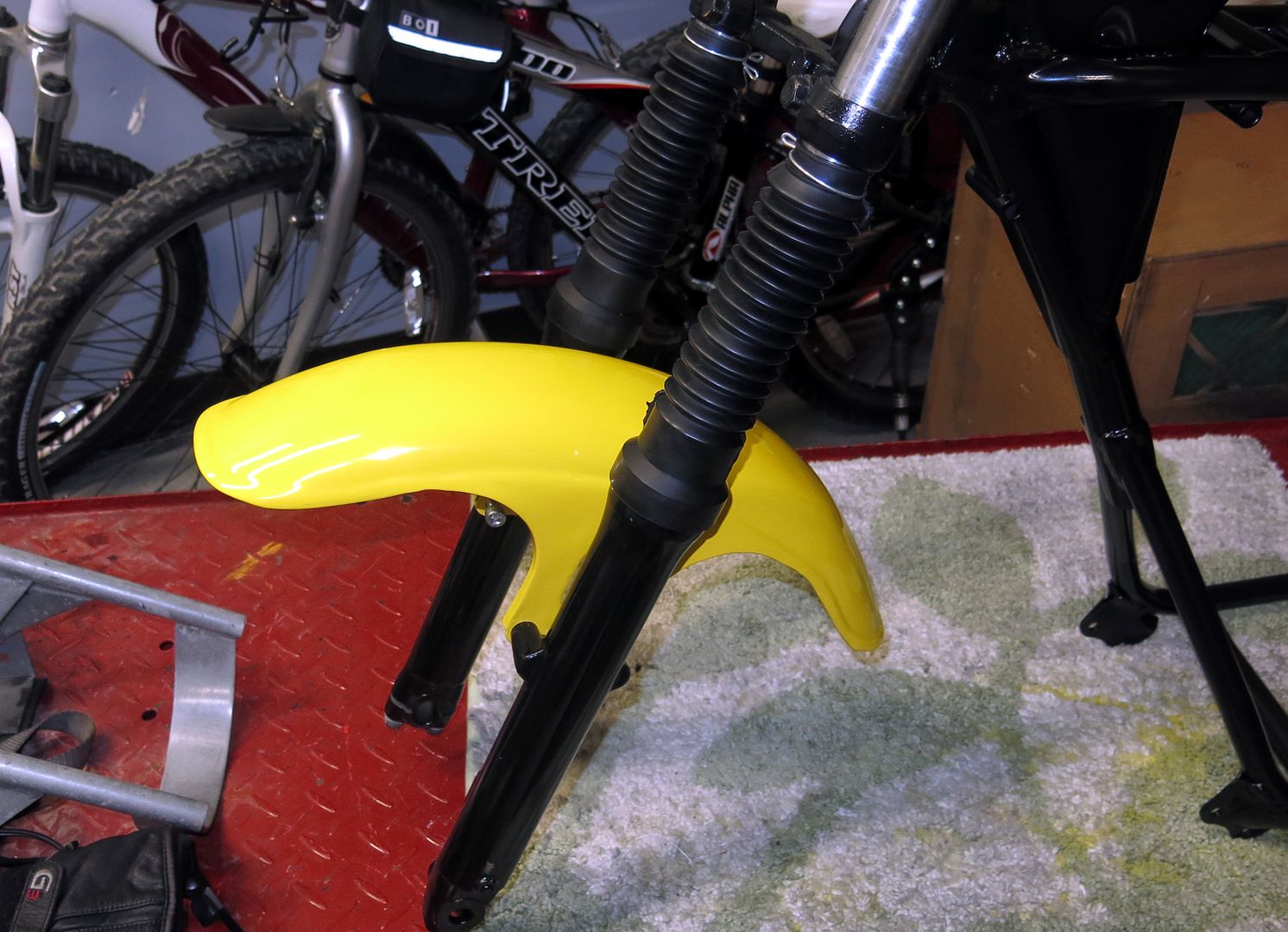
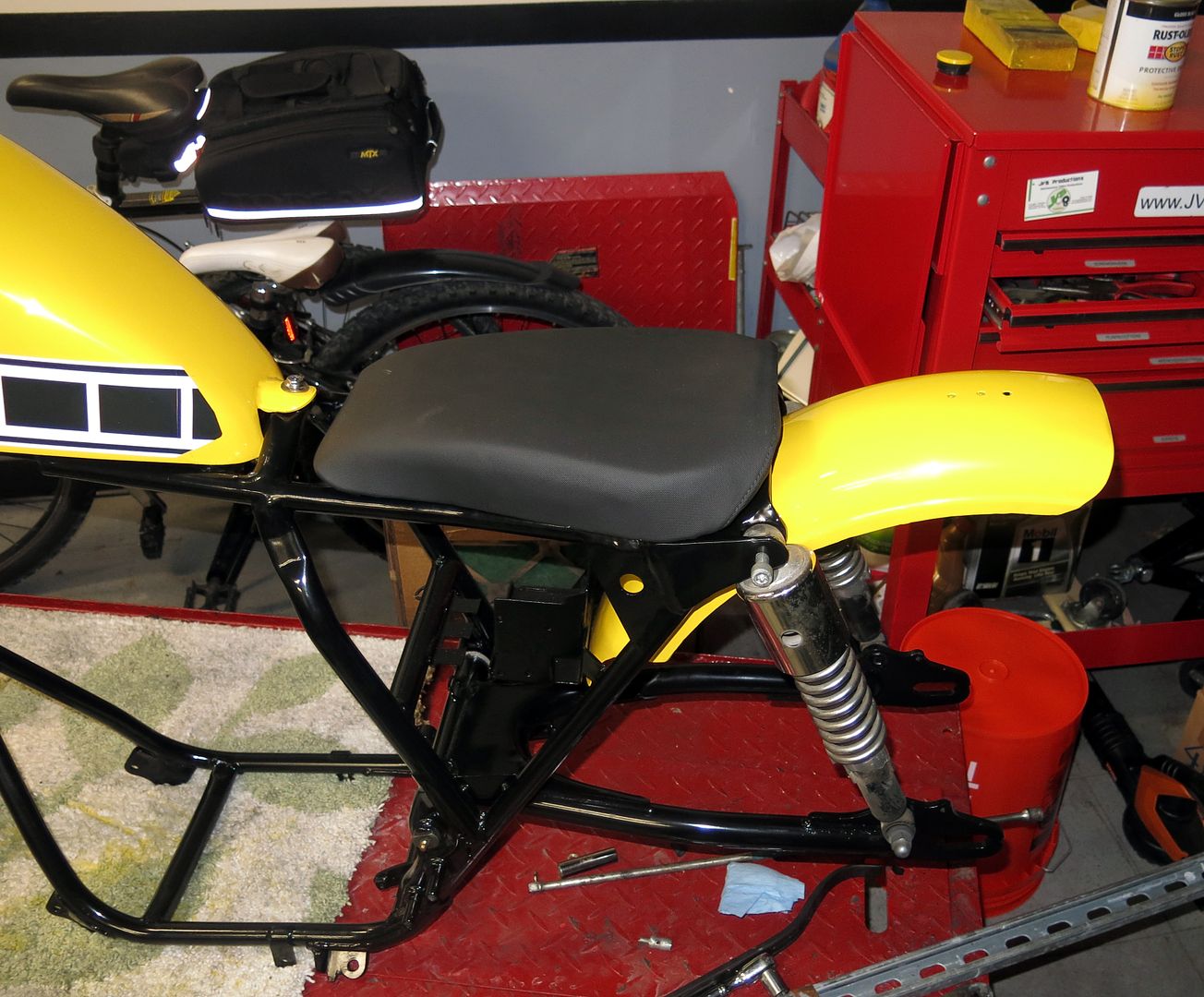
Finished the paint on the tins. I put them on the frame to see how they would look, with the new decals, and to get them out of the way for the next phase, the motor!
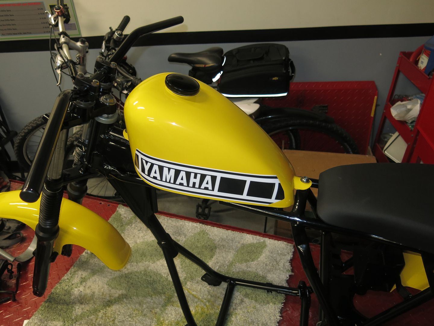
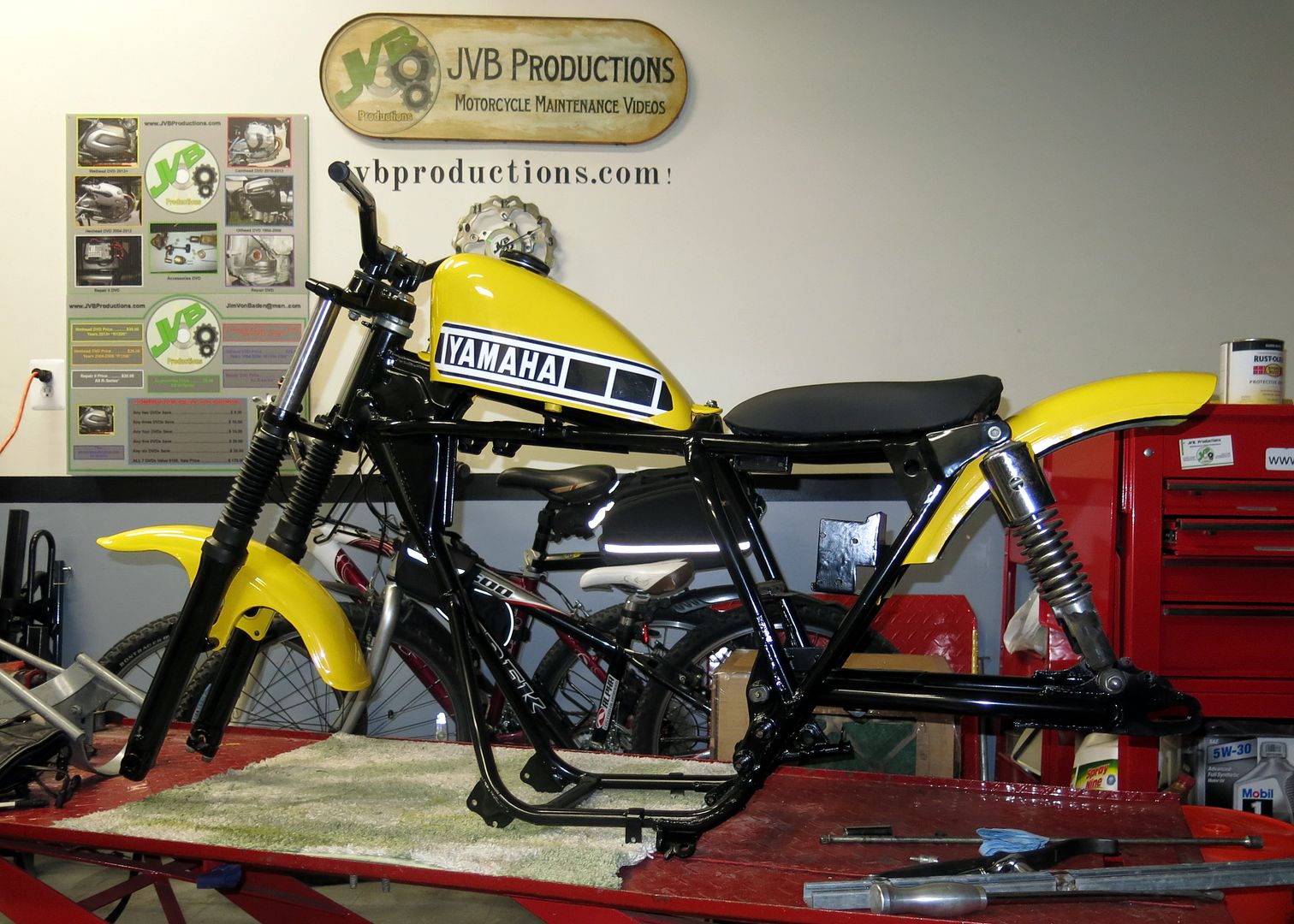
Looking good Jim! I have always like that colour scheme.
Jones
XS400 Enthusiast
How much u want for them? Including shipping to 53208. Milwaukee If possible.
JimVonBaden
"Cool Aide"
How much u want for them? Including shipping to 53208. Milwaukee If possible.
Let me check on shipping, but say $50 plus shipping.
Jones
XS400 Enthusiast
Cool. PM me when u get a shipping quote and we can set up something through paypal
JimVonBaden
"Cool Aide"
Got started on the engine clean-up. Bonus, the ignition has been converted to electronic type.
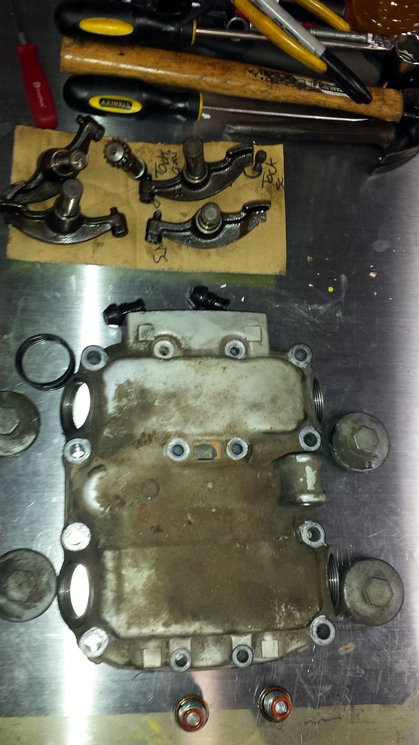
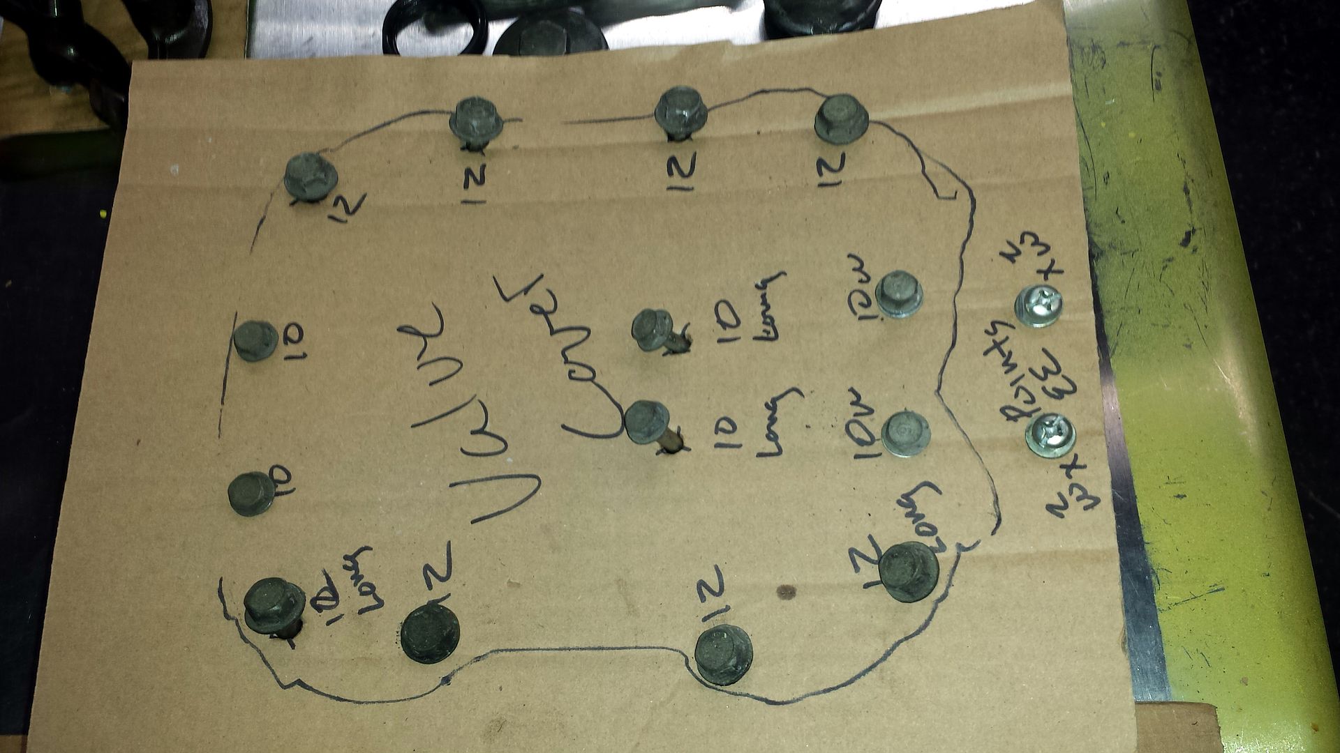
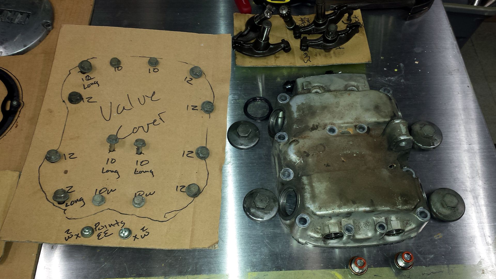
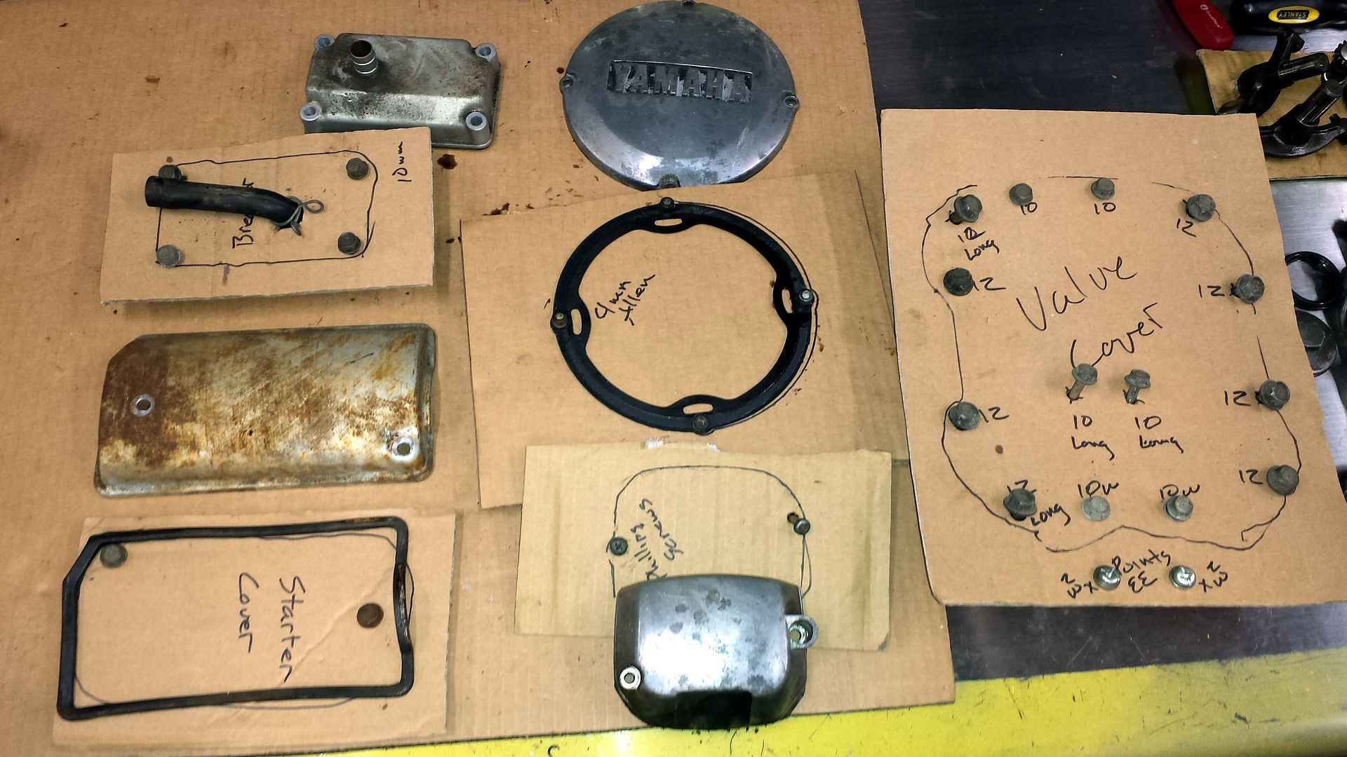
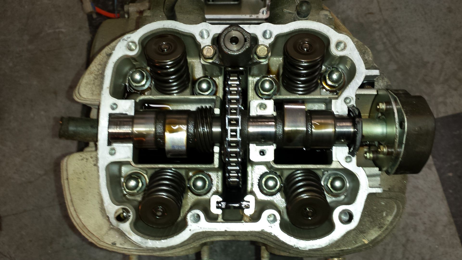
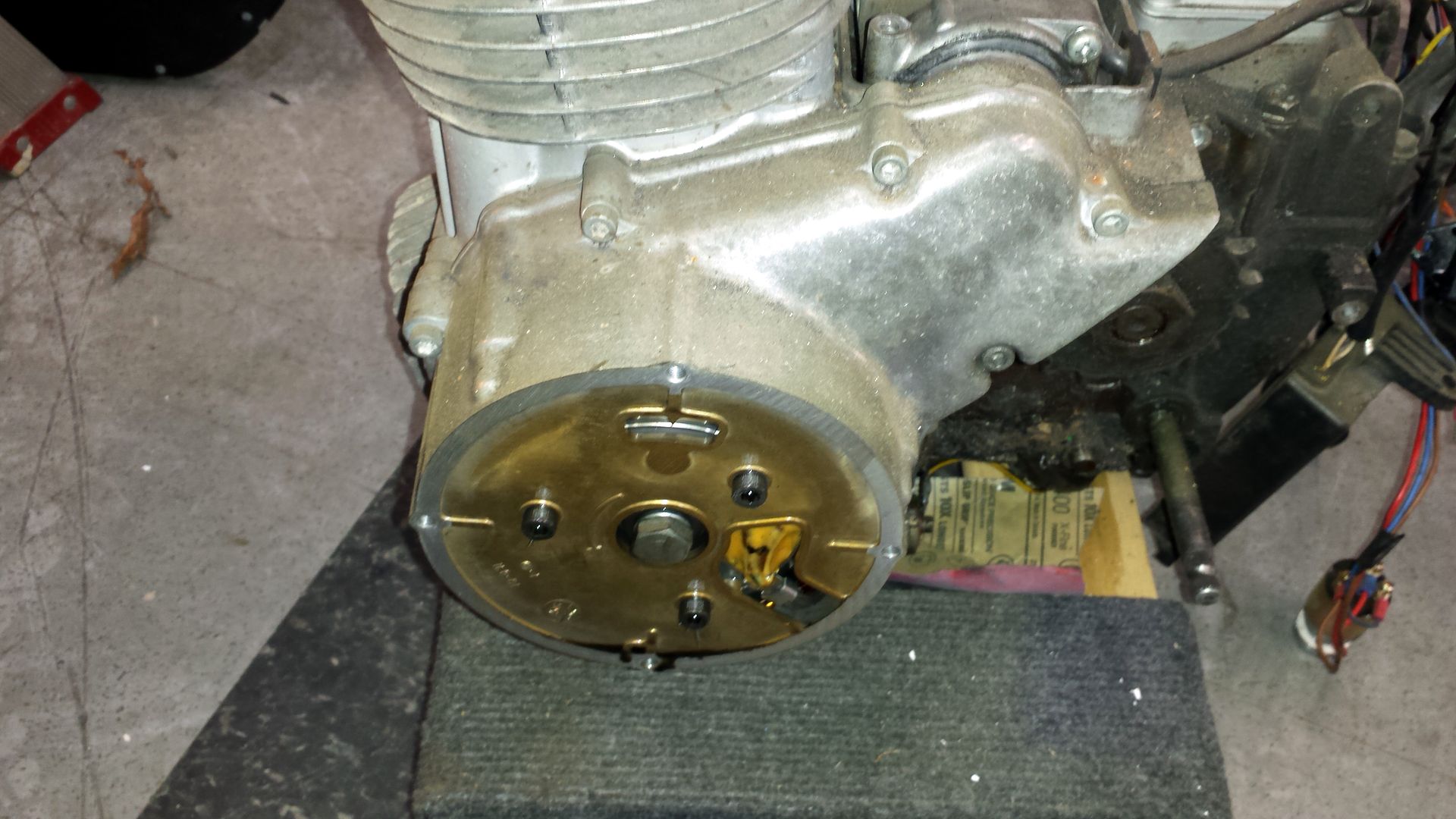
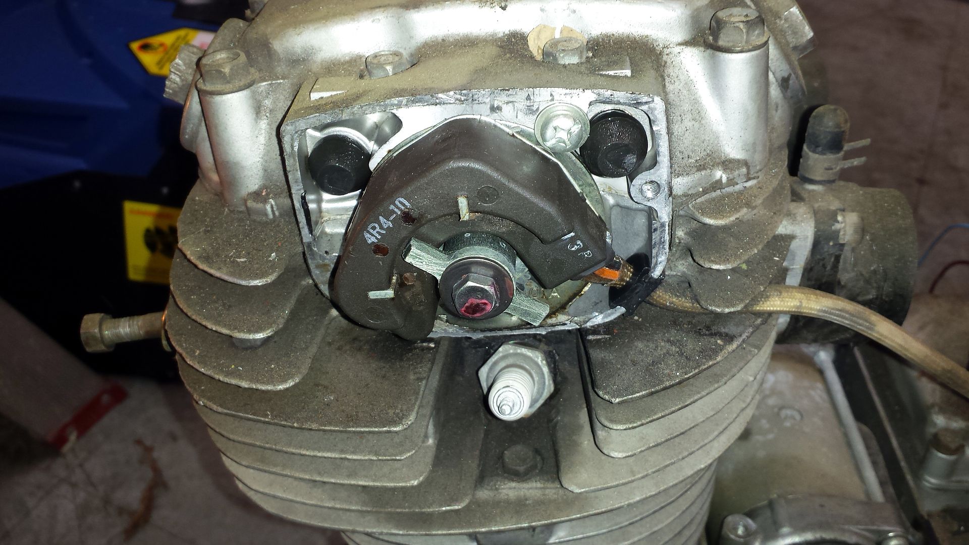
Lots of work to get it pretty, but I have nothing but time, yeah right!
Lots of work to get it pretty, but I have nothing but time, yeah right!
rshutchinson
XS400 Addict
80-82 came with electronic ignition. It was the previous models that had points.
Similar threads
- Replies
- 15
- Views
- 3K