Instant drop in voltage w/ key on

dO-bOy

Woohooo!
Messages
265
Reaction score
1
Points
18
Location
Vancouver, BC
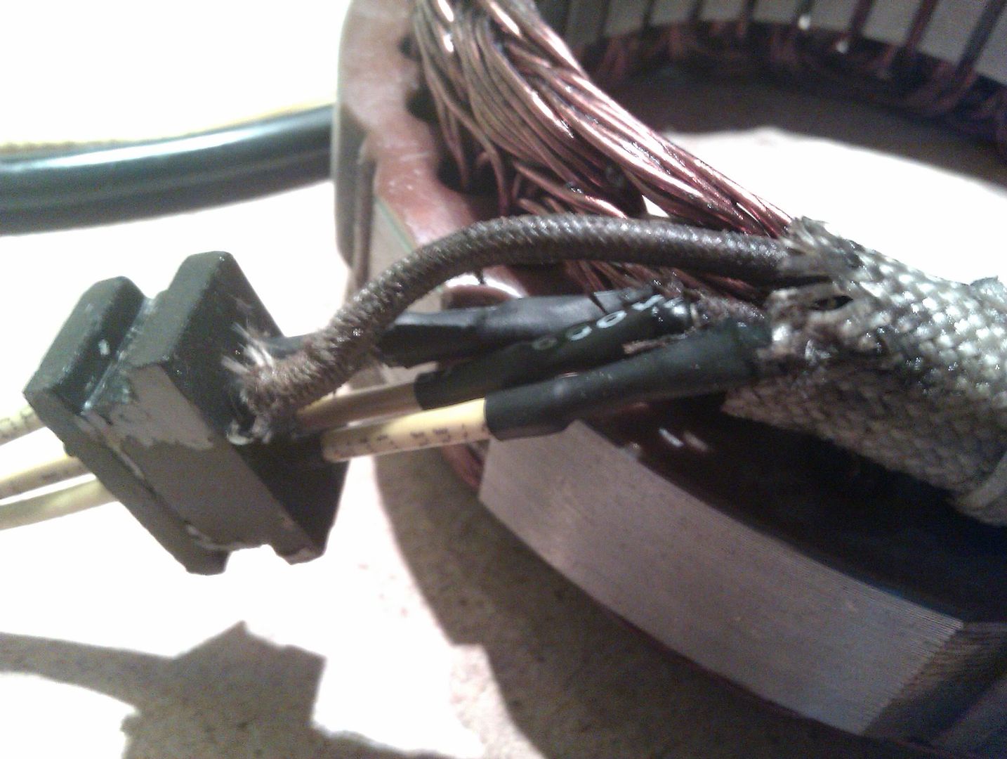
- all original electrical components
- kickstart only (solenoid removed, using cig. Pack 0.08ah sized battery)
- brand new battery

Battery reads 12.4-.8v by as soon as I turn the key to on, It drops down to 10.3ish. I'll kick the bike over and it'll stay at 10.3 for a minute, then slowly drop voltage.

I'm trying to go through the manual troubleshooting section, but I'm very electrically noobed. Any help would be appreciated. Thanks bro's!
 
Chemically speaking, the battery voltage will always drop when there is a load on it. 10V seems low to me, but that could just be due to the small capacity of the battery (my 0.4V drop on a 12Ah roughly corresponds to 1.6V drop on a 0.8Ah battery). That being said, the alternator should be charging to ~14V when it's running, so it looks like your bike is another victim of the XS' electrical gremlins. :mad:
 
might not be enough voltage to power the field coil!

I use a 2.1 amp Alarm battery

temp fit a bigger battery to confirm
 
I appreciate the quick responses guys! I'm always slow to post, search first and go through the manual, then ask questions. But i find it funny that after months of feeling like I'm crazy, I found the gremlin!

I went to physically check out the alternator after I posted and as I was taking the cover off, I noticed alot of shavings. It looks like the PO ran the starter whole the bike was running and sheared off some teeth. Amazingly I rode it like that for 2 months last year (alwaysbeen kick only for me) with that crap bouncing around and eventually wreaking havoc on the wires that come off the coil

Does this look repairable? Can I take the sheathing off to fix the short wire? Will shrink wrap fit and seal inside the grommet?

Thanks in advance!
 

Attachments

  • IMG_00000127.jpg
    IMG_00000127.jpg
    107.4 KB · Views: 173
Anything is repairable, depending on skills and tools.

I guess my first question would be how much for the replacement, so is it worth it? I can't tell - is that sheathing fabric? You'd need to repair it and keep the wires from shorting, I would think...
 
The wires are completely broken, I guess I'm asking because it looks beyond my soldering skills. I'll clean it up and take it to an electrician. I have friends that do it and a used stator is over $120 of ebay!

I don't want to spend much because I'm considering upgrading the system this winter. Thanks for the insight!
 
dood. You can do this. It's really really easy.

Soldering is melting metal with a hot tool. It's sort of like melting wax, but when it cures, it's an electrical connection. It's not mystical. You strip the wire away, melt solder onto both wires, heat them, touch them together until they bond, and remove the iron. It's cake. You'll spend more time being perfectionist about doing it than it takes to heat a joint and bond the wires.

Anyone that can solder can do this for you. The right wire will be around 18 gauge. Drewpy already covered this if you look at his posts. Get the tinned thinwall boat wiring. It's super durable.

Don't be mystified by that hempy looking stuff. it's actually a fiberglass covering they put over the wires so they'd stay out of the way of the stator. Just get some clean wire exposed so you have something to join the new wires too, and then pull the old ones out and push the new wires into the holes in the rubber grommet. Solder the ends together at a 45 degree angle so you can pull them out the rubber grommet when finished. If you're skilled you can slide heat shrink over the wires before you solder and then seal them up.

You can leave the yellow wire alone. It only gets used in stator diagnostics. It connects to nothing. No need to solder it. Just replace the three white wires and you'll be golden.

Good luck.

Drewcifer
 
I'd also recommend that you practice soldering junk wires together two or three times so that you get the hang of it, that way you have way more confidence when you go to do the real thing. :thumbsup:
 
Yeah. Pseudo's advice is very good. You learn to solder practicing. Ultimately, though, it's not too hard. You can learn on youtube if you want.
 
The nice thing about soldering is that if you mess it up, you just reheat and separate the wires. It's non-destructive, as long as you don't burn anything down with the iron.
 
You can leave the yellow wire alone. It only gets used in stator diagnostics. It connects to nothing. No need to solder it. Just replace the three white wires and you'll be golden.

Good luck.

Drewcifer

I pretty much love you guys. I'm in the process of doing this now but wasn't sure of two wires which break it went to. But it's great to hear the yellow isn't crucial. If I guess wrong which is 50/50,i can just switch the time connectors.

I've soldered before but its been hit or miss. Talked to my friend today and he discovered my iron is buggered :doh:

Will post pix of my handywork
 
I finished wiring up the stator but I'm missing an ohm reading on one white wire, but I'm getting a reading from the yellow diagnostic wire. That doesn't sound right.

Should I be getting a reading from the yellow wire? Will I screw up the rectifier if I mix this up? Or can I switch the wires around until I get proper charging?

In hindsight, I should also mention, one of the coil wires on the stator looked almost broken and kind of mashed down from whatever foreign object was flying around in there. Should I be shopping for a new stator?
 
Last edited:
You can get a reading from your yellow wire. It can happen. I've only heard it mentioned in use in a flowchart for diagnosing stator problems (it was described as "extra wire or neutral wire" since some other manufacturers use yellow where yamaha uses white. Hence "extra" wire.)

You can use it to measure resistance against the other winding since the yellow goes to either stator ground or stator winding. I can't remember.

If you can send a picture of that stator damage we can make the call. Hopefully you luck out and it just needs to be resealed with epoxy. You can test the damaged section by probing it with the ohmeter set for continuity (or high ohms) and touch the ends of the wires at the socket.

You have to test all three because you don't know which of the windings is exposed off hand. hopefully that damage is only compressed but not exposed. Even so, if it is, stators are not hard to come by. A used one will work fine. I ask ebay sellers to ohm test them before I commit to buy. They take a few days but always do.

There should be no continuity at all because the windings should be encased in epoxy before they're wound. If you DO get continuity at the damaged spot, You can I think reseal it up with epoxy.

Until I see the pic of the damage (well lit, up close) I can't say. I suspect there's still a broken wire you can't see. Send us a pic of your new wires soldered in. We might see what you don't.
 
It doesn't matter which way the white wires are wired, the only difference between them is the phase offset of the AC voltage. So long as each goes to the rectifier, the system will work. The yellow connects to each white where they all meet inside the coil. As for the damaged spot, I didn't see it in your pic but it is probably the culprit. If just one or two wires are broken there then you can repair them, but try to make sure they don't protrude more than the others. The best way I've found to remove the insulation to magnet wire is to scratch it with a razor, but be careful if you decide to do that so you don't do it to the good wires. After you fix each wire, you need to re-insulate them: an oil resistant epoxy on a q-tip should work out well here. Do that one at a time to make sure you don't let any of them short together.
 
Well I guess that doesn't look too good now that I think about it haha. I'm a bit lost though, how would I go about fixing this with epoxy? Just mush it in top?? I've called around locally and the salvage yard here has one for $80. I'm probably gonna run and grab it tomorrow.

I'm a big forum guy if you didn't know. I was highly involved in car drifting forums but the difference here is I'm receiving rather than giving. It's refreshing to know there are others so willing to share their knowledge and I hope you all know how appreciated your time is.
 

Attachments

  • IMG_00000130.jpg
    IMG_00000130.jpg
    171.7 KB · Views: 178
  • IMG_00000132.jpg
    IMG_00000132.jpg
    108.2 KB · Views: 149
Do they show connection to any of the white wires on the voltmeter? If so they're exposed and you can get it resealed with oil resistant epoxy. I think there's a 3m spray you can use for it.

http://multimedia.3m.com/mws/mediawebserver?mwsId=SSSSSu7zK1fslxtUo8_94xMSev7qe17zHvTSevTSeSSSSSS--

If you're in a rush, sure the salvage yard. I saw the stators on ebay a week ago for only 45 dollars so if you can wait...ebay.

By the way, nice tight rewire! :)

If you didn't get a chance to lift the stator out I'd do so. Make sure no metal shavings and pieces of Sh*t are trapped underneath or inside the winding loops. Just try to keep it straight up and down as you remove it so it doesn't snag on the stator case.

Remember it has to lay very flush for it to work correctly when it goes back in.

Proud of you for going back in and checking though. You're nearly in the zen of motorcycle maintenance where you just let go and work on it with detachment. The feeling when it suddenly works as it should is the best.

Safe Riding!
 
On your stator, being a three phase stator you have three white wires, as long as the three white wires go to the rectifiers three white wires which white to which white don't matter.
The three sets of windings in the stator have a common junction point. The yellow wire is hooked to this common junction.
Yamaha used this set up on several different bikes.
While the engine is running this yellow wire has a voltage of around 12-15 volts. This is unregulated pulsing AC, Almost DC but not quite.
On some bikes they run this yellow wire to a relay and use this voltage to trip the relay as long as the engine is running.
The relay is used to control power flow to the starter. When the engine is off the relay contacts are closed allowing power to flow to the starter relay. Now when you hit the start button the starter cranks the engine, starting the engine, As the engine starts the alternator makes electricity. Some of this electricity flows out the yellow wire tripping the relay, opening the contacts, turning the power off to the starter relay, stopping the starter and preventing it from working as long as the engine is running.
On some bikes this relay also sends power the the headlight, turning the headlight on after the engine starts. This keeps the headlight off so all the battery power can be used to start the bike and once it starts making electricity it turns the headlight on.
On the XS400 it don't need this because of the starter clutch. But the yellow wire is there and can be used in testing.
Leo
 
Thanks buddy's! I removed the stator to do the rewiring, the tip to solder them at an angle helped a ton. I ended up grabbing a new (to me) stator from the hunkered. Been riding for 2 days now
 
Back
Top