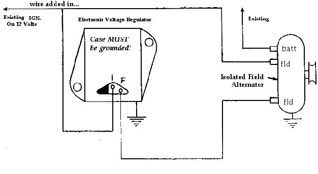
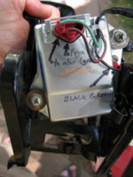
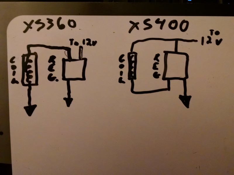
OH. So that means the brown wire (from the harness/fuse) has to connect to the black wire (from the field coil) before they both connect to the pin on the regulator. If that is the case, I can just jumper them across from the pigtail connection, and remove the black wire from the pigtail, and ground the case separately.
I was grounding the black wire like the original picture on the left. I wonder if the black wire grounds anywhere else, like near the coil? From your diagram, it looks like it... but there is that black wire that runs wire back from the field coil. I will check it all for continuity tomorrow.
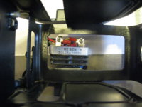
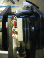
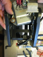
Yes, the stock regulator is a mechanical one. It is labeled "NiponDenso" and says"026000-2790" on one line, and "12V 2P" on another line. It has two pins on the back, that go to the green and brown wires on the harness, and the solid black that comes from the field coil goes to the case and ground.
So there must be a fundamental difference in the way the two regulators adjust the voltage with ground...?
How was I checking things?
- I tested the field coil just by running a hot wire from the positive terminal to the green wire of the field coil (with the v. regulator unattached). Then I put a wrench near the field coil and it stuck to the crankcase.
- When it was running I was checking (with a voltmeter) the green wire out across to the negative on the battery. Everything was hooked up, I was just checking from the connection where the pigtail connects to the wire harness. The wrench wouldn't stick.
- I watched the voltage drop just by checking across the battery terminals as the bike was running.
If I disconnect the regulator, can I jump a hot wire to the green field coil wire while it is running, just to see if it will excite the coil and charge?
Thanks for your information and help!
")