RR38 Regulator Rectifier - Where to buy

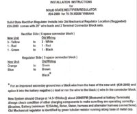
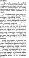
Correction, Electricity made in the stator is AC. That AC current is going "every which way" The Bike is a DC bike. So the first stop for the electrons is the rectifier. the recifier has 3 Diodes. A diode makes electricity goes one way only. 3 phase is the number of white wires coming off the stator. if for example someone put 6 wires on the stator, you would have 6 phase. (bogus example) The Rectifier is designed so that you one phase will provide X amount of AMP's. and if the Draw becomes too much, the 2nd diode will provided the additional AMP's. then if the Draw is Maxed, the 3 phase will cover the rest.

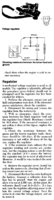
If you look at the diagram for the 80's model, you will see the white wires split off, (to the headlight) even after that split is a diode.

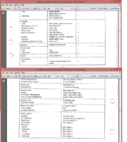
If you look at the Manuals, the engineers put in the current and draws of all the lights, for the calculations, They used that to give us the minimum needed stator, as well as turn signal canceling device. So it is about Math, and I am not good at that. So I gues in attempt to answer your question, the engineers, look at the current technology (1980) and what is it going to take to run all the lights, and keep the bike running. Can we save $$ by going going cheap? Where is the Need/Want spot at?

AC Alternating Current
DC Direct Current

Thanks for the info, it is useful - however, with that bit you quoted, I meant that the rectifier diodes appear to be blown, because the current goes through in every direction I tested with the ohm meter.
 
OK, this is good advice for wiring our own rectifiers. Excuse my ignorance on rectifiers (and our bikes), I'm just not sure how the max amps or max voltage affects things that are not maxed, or events like if somebody charges the battery on the bike, or something like that. Is it OK to run a rectifier that is 30 or 60 or 100 amp rated? What if it is 1600 volt rated? Is it just more money, but the effect is the same? After reading Arfstrom's post again (above), there must be some sweet spot with each diode and current output, otherwise we would just need one big diode and leave it at that.

Now if we were searching for parts, either old or aftermarket regulators/rectifiers, would the rectifiers be interchangeable for the following bikes: XS250, XS360, and XS400 from 1971-1985?

I don't know all these bikes, but found somewhere (sorry, I can't find my link) the rr38 or zj-rr38 fit these bikes for these years. So I am assuming, if these guys listed it right, that all are interchangeable within these bike models and years? Anybody with knowledge of the bikes know for sure?

r38 has: 3 x white, 1 x red, 1 x black, 1 x green, 1 x brown

Mine is the similar to the rr38 (not exactly), it has:
3 x white, 1 x red, 1 x black, from the rectifier.
1 x green, 1 x black and one black with red stripe (ground?) from the voltage regulator.

I have uploaded images of my rectifier with connector, and my voltage regulator with connector for reference. Both have the original part numbers on them.
 

Attachments

  • IMG_9356.JPG
    IMG_9356.JPG
    166.4 KB · Views: 366
  • IMG_9357.JPG
    IMG_9357.JPG
    136.8 KB · Views: 330
  • IMG_9355.JPG
    IMG_9355.JPG
    214.5 KB · Views: 365
  • IMG_9358.JPG
    IMG_9358.JPG
    85.4 KB · Views: 374
Last edited:
Now if we were searching for parts, either old or aftermarket regulators/rectifiers, would the rectifiers be interchangeable for the following bikes: XS250, XS360, and XS400 from 1971-1985?
The first image I put up has the name of the Recifier, I really don't know what it means as far as 'L' wave. as you can see, this weaken stator, is just what the brains said this bike needed. So if you are going to shop between models, download the manual 45 meg manual. It is the supplemental version, for all the models. Keyword Rerun manual, I just re-ran it about a month ago.

I know I am using the model for a car, It is listed in my photo album. Got it for about 10 bucks I think from Oriellys auto parts, and the Pigtail, (KIS) Keep it Simple

There is always another way to skin a cat, I just don't know all the different ways!
 

Attachments

  • Rectifier info.png
    Rectifier info.png
    126.5 KB · Views: 368
  • x400oldVoltageRegulator.jpg
    x400oldVoltageRegulator.jpg
    181.7 KB · Views: 337
  • x400oldRecifier.jpg
    x400oldRecifier.jpg
    116.9 KB · Views: 350
Thanks, these are helpful!

I may be going the $8 Chinese SQL25A rectifier route (or (re)building my own with diodes - I can source these in town here if I figure out which diodes I need), and the car regulator (I don't know if my regulator is shot just yet, but people seem to think I should replace regardless). I just can't bring myself to spend 100-150 dollars for these simple parts.
 
arfstrom, and others, A 3 phase rectifier has 6 diodes inside. All the AC from the stator is rectified into DC. The rectifier doesn't change the amount of diodes used with different current draws.
I wish I had diagrams to post up. It would be simple to explain it that way. Try googling 3 phase rectifiers.
The regulator controls the current flow through the field coil. This controls the stator out put.
The reg reads the voltage on the brown wire. The brown wire gets it's voltage from the battery. If this voltage is below the reg's preset, About 14-14.5 volts It turns on the current flow through the field coil. This excites the stator to produce the AC that gets rectified and sent to the battery. As the battery voltage rises to the reg's preset, it turns off the current flow. This stops the charging, The reg cycles off/on hundreds of time a minute to maintain the voltage at the preset. That's the old mechanical reg's. The new solid state having no moving parts cycles much faster, like thousands a minute. This does a better job of maintaining the voltage.
On testing a rectifier the diodes will pass electricity both ways.
You test by hooking the red lead to the red rectifier wire, now touch the black lead to the three white wires, Write down the readings.
Now hook the black lead to the red wire and touch the red lead to each white wire. write down the readings.
This tests one set of the diodes in the rectifier. You need to repeat this test using the black wire on the rectifier.
As you test each diode both ways you will get a low reading one way Like 75 to 150 ohms, and a high reading the other, Like 200k ohms. Maybe even infinite.
As long as the high reading is at least 10 times as large as the low reading the rectifier will function.
Leo
 
Last edited:
I have goggled it, and am on the verge of understanding at least this rectifier... I do see six diodes in the rectifier on the wiring diagram for the XS360C.

I am in the process of dismantling mine. Does anyone know what type of diodes are in there?

Although somewhat frustrating when trying to get things working quickly, It is interesting to know one's machine this intimately.

Thanks,

Dan
 
So according to all we have gone through so far, this rectifier/regulator (linked below) SHOULD work for the XS250, XS360, XS400, as well as the listed XS650?

http://www.xs650direct.com/products-30.html

about 3/4 down the page there is a replacement rectifier/regulator Part #24-2089.

If this fits the 250s, 360s and 400s, it will be useful for those of us in Canada!

Thanks,

Dan
 
Yup, your right, its that reading and paying attention. In the 3rd image, of the Manual copy, that in the very first sentence in the first paragraph, it said it is a 6 diode bridge. See if I go to that school that taught me to read! ;)
 
The #24-2089 is set up for the early XS650's. That reg/rec controls current flow through the field coil by sending current to the field coil then to ground.
The later, 80 up controlled the current flow by grounding the field coil. The field coil got current right from the brown wire.
To use that reg/rec you would hook it up as in these directions I'll post up.
The field coil hooks up with a similar color code. If not Just hook the orange wire to one wire for the field coil, the other wire of the field coil to ground.
Leo
 

Attachments

  • Rectifier%20Regulator%20Instructions.jpg
    Rectifier%20Regulator%20Instructions.jpg
    161.5 KB · Views: 425
I'm still waiting for the rectifier via amazon.

However, I have got the voltage regulator set up. I wanted to mount it in a similar spot, so I modified the case a bit. Had to tap in some new holes in the battery/air filter holder. This type is linked to Leo's advice. I used the 75 Dart type of rectifier. The parts guys here in Saskatoon at Part Source had some cross-references from different maufacturers. There was the original VR295, but it cross-referenced to a VR125, and a VR733 by Victory Lap which is the one they had in stock for $20.

Here are some pics for anyone interested. 1&2 The mounted regulator, using the original rubber mounts, but which probably aren't that effective as vibration dampeners because there are some tight edges in there.

3&4 The adjusted mounting holes for the regulator. On the battery holder, I just drilled and tapped them. On the regulator, I drilled them out, snipped the opening, and filed things smooth so that the rubber mounts fit in there.

5 The tap I needed to put the original bolts in the new holes. M6X1.0. Not as strong as the original welded nuts, but it seems OK for now.

Oh, and the wire hookup, the black with red stripe on the pigtail goes to a brown wire on the other side of the connector, the same as Leo mentioned earlier.
 

Attachments

  • VRegMounted.jpg
    VRegMounted.jpg
    150.8 KB · Views: 358
  • VRegTopView.jpg
    VRegTopView.jpg
    133.3 KB · Views: 360
  • VRegBolts.jpg
    VRegBolts.jpg
    198.1 KB · Views: 360
  • VRegDrilled.jpg
    VRegDrilled.jpg
    147.7 KB · Views: 351
  • M6x1TAP.jpg
    M6x1TAP.jpg
    98.2 KB · Views: 321
Last edited:
I'm glad you like it. I appreciate the help you have all given, and would like to let people know what worked for me. I will post when the rectifier comes. I still haven't put everything back on the bike, so I hope it all fits the way I have mounted it :).

D.
 
On a side note I just bought a regulator for a later model; the harness is opposite (female versus male).

Is there a way to convert between these two styles? I currently have the old style on my '78 and want to use this new style. Grafting a new harness on is no big deal but the wires are different colors or are in different positions; each has 3, however.
 

Attachments

  • regu.JPG
    regu.JPG
    207.6 KB · Views: 330
  • regu2.JPG
    regu2.JPG
    286.5 KB · Views: 341
Yeah you can use that reg no problem BC. Black to black, green to green, the last 2 wires should be different colors but will go together.
 
On a side note I just bought a regulator for a later model; the harness is opposite (female versus male).

Is there a way to convert between these two styles? I currently have the old style on my '78 and want to use this new style. Grafting a new harness on is no big deal but the wires are different colors or are in different positions; each has 3, however.

On my bike, the black with red stripe on the regulator side of the connectors goes to a brown on the wire harness side. Check your bike, it might do the same thing. Black is ground on both sides of the connectors, and green goes to green on both sides.
 
OH, and on some trucks I have worked on before, sometimes, if you are careful, you can pull the metal connectors out of the plastic connector head (it might require squeezing, and pulling or some such manipulation), and then push them into the new connector. That way you don't have to splice wires, and things look a little neater when you are done.

And just a question - what did Leo send a few posts back about a change in how the regulators worked in the '80 and up bikes? Does this make a difference to setting up these regs?
 
Would there be any interest in a regulator/rectifier combo that's designed for our charging system specifically? I can build one that's fairly small and is more efficient at idle and low rpms. Would be around $60, and you'd have to splice in the connectors on your own. Also you'd need to find your own place to mount it, but shouldn't be too hard. Wouldn't get too hot due to the design. If more then 10 people are interested I'll work on getting some built.
 
You could make a new thread and start a pole for interest.

I think, however, that the key to success here is making it plug and play. Is there any way you can get a plug that matches the oem one? Even if it costs more I think it would increase interest significantly. Most people don't want to do the wiring even if it is very simple.

When I looked around I honestly could not find one that is plug and play within the united states for less than about $95 not including shipping: http://ricksmotorsportelectrics.com/part/10-404/NzhZYW1YUzQwMA==

The only other place on the internet in the USA wanted around $140 for one.

Any less and you're buying from China direct and they aren't even available on Ebay; you have to go through Aliexpress or whatever.
 
The connectors are available, but the price would go up a little. The only reason I wouldn't want to put them on is for convenience of the end user. I can leave a very long wiring tail on so the builder can put it wherever they want and trim the wires as needed. If I toss a connector on, some might end up with an unnecessary long loom to tuck away, or end up having to chop it up anyway
 
Back
Top