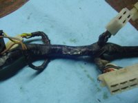
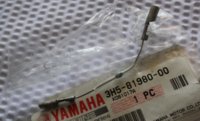
The diode not being there is probably one of the reasons why things have burned up and not working. Here is a pic of a 81 harness I have that shows a diode. It looks like it was replaced at some point because it is a different type than what my 80 looked like.
-
Enjoy XS400.com? Consider making a donation to help support the site.
XS400.com receives a small share of sales from some links on this page, but direct donations have a much greater impact on keeping this site going.
You are using an out of date browser. It may not display this or other websites correctly.
You should upgrade or use an alternative browser.
You should upgrade or use an alternative browser.
Igintion problem
- Thread starter Scorpio1963
- Start date
If you order a new one. If will have clear cover, two bullet connections. roughly 4 inches long. Of course radio shack has diodes for fifty cents
Well guess I will order the diode to take the place of the copper wire,things that po do baffle the crap out of by trying to take short cuts only causes more problems
Notice this is on the electrical #1 diagram. if you go searching for it. Note, Copper has no diode properties. If you have you multimeter, start doing random checks on the coils, and other items. Stator, VR ... since you have a waiting period, you can atleast see if anything else got killed. the relays can wait till your running, (headlight issue, if you have have an issue, you could test the continutiy of your headlights.) ((Perhaps its time to upgrade to HID???? or something?))
http://www.boats.net/parts/search/Yamaha/Motorcycle/1981/XS400SH/ELECTRICAL 1/parts.html Part 28
28 3H5-81980-00-00 DIODE ASSY $12.99 $8.49 1
Best image of what it should look like.
http://www.ebay.ca/itm/YAMAHA-XS400-XS-400-ELECTRICAL-DIODE-GENUINE-OEM-1980-1983-/400698960805
http://www.boats.net/parts/search/Yamaha/Motorcycle/1981/XS400SH/ELECTRICAL 1/parts.html Part 28
28 3H5-81980-00-00 DIODE ASSY $12.99 $8.49 1
Best image of what it should look like.
http://www.ebay.ca/itm/YAMAHA-XS400-XS-400-ELECTRICAL-DIODE-GENUINE-OEM-1980-1983-/400698960805
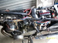
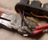
ok here is some pics today while working on my harness.
You will notice a pic with most of my harness unwrapped while looking for a missing diode.
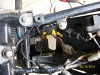
Another pic where my after market rectifier/voltage regulator the crappy wiring job the po did.
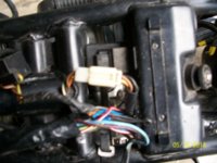
Theres a pic of white plug that I was trying to take apart but no matter how hard I try it wont.? on this is it supposed to come apart.
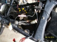
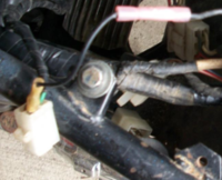
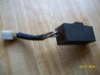
Then theres a pic of a 4 wire plug in that has the ground wire that was attached to the battery box. A ? on this would be how do I wire it or is it fine being grounded the way it was.
You will notice a pic with most of my harness unwrapped while looking for a missing diode.
Another pic where my after market rectifier/voltage regulator the crappy wiring job the po did.
Theres a pic of white plug that I was trying to take apart but no matter how hard I try it wont.? on this is it supposed to come apart.
Then theres a pic of a 4 wire plug in that has the ground wire that was attached to the battery box. A ? on this would be how do I wire it or is it fine being grounded the way it was.
Attachments
Does anyone know the value of that diode and is bidirectional or nondirectional?
Also Im thinking that the diode was there in the copper piece of wire but when it blew it desinigrated.
Also Im thinking that the diode was there in the copper piece of wire but when it blew it desinigrated.
Its one way. The diode takes AC current, and makes it DC.
White wire is AC, Alternating current.
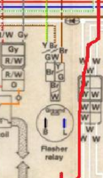
on the other side of the Diode, or Rectifier the energy is turned into DC, Direct Current. Once the current gets past the Diode, All the white wires get changed to DC. The white wire on the diagram, that I clipped out earlier, has a diode, then it goes to the relay, for pushing more power to the headlight system. also known as a dedicated phase, Okay TMI. If you look at the three white wires, That means our stator is 3 phase generator. TMI, that is not important right now. So to answer your question, the power is one-way after the diode/rectifier.
Non alternating current or the opposite of AC, is Direct current, aka, DC one way.
White wire is AC, Alternating current.
on the other side of the Diode, or Rectifier the energy is turned into DC, Direct Current. Once the current gets past the Diode, All the white wires get changed to DC. The white wire on the diagram, that I clipped out earlier, has a diode, then it goes to the relay, for pushing more power to the headlight system. also known as a dedicated phase, Okay TMI. If you look at the three white wires, That means our stator is 3 phase generator. TMI, that is not important right now. So to answer your question, the power is one-way after the diode/rectifier.
bidirections is same as AC/ Alternating currentbidirectional or nondirectional
Non alternating current or the opposite of AC, is Direct current, aka, DC one way.
Last edited:
This looks like a plug from the voltage regulator. Yes, it is fine for it to be on its own ground. Not optimal, but it works. What might not work is the multiple wire splices. The crimpers that are normally found with these type of splices, are crap. Fine for speakers, but not for a bike you want to keep running. during all phases of riding, the bike.
Attachments
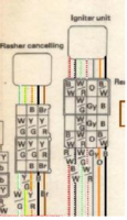
I think this one is your flasher wires according to the 81 scheme, is Black,blue, going to Yellow green, brown, and brown white wire
It should come apart, but I think its just a flasher relay, its nothing to worry about, till you decide to do a LED upgrade.
It should come apart, but I think its just a flasher relay, its nothing to worry about, till you decide to do a LED upgrade.
Attachments
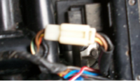
Well I just wanted to open so I can check the connections for corrsion.Darn thing doesnt want to budge.It also by the way it looks and feels seems like it got hot.The two halfs were almost melted together and I had to use a raser blade to run through and seperate the seams.I got it to start wiggling around but its been stubborn and doesnt want to come apart.
Also on the pic where the rectifier was wired in and spliced together with the yellow connectors how would I go about cleaning that up.It looks like crap,does the job I suppose but theres got to be a better way of connecting the wires together.
Also on the pic where the rectifier was wired in and spliced together with the yellow connectors how would I go about cleaning that up.It looks like crap,does the job I suppose but theres got to be a better way of connecting the wires together.
When I did the LED conversion, I did the Metric kit thing, from superbrightLEDs, and this is the result. I pre cut a heatshrink, and then I cut the wire, combined them, (both sides) a drop of solder on the wire. I was using the wire cutters for a heat sink, so that the excess solder doesnt burn something that is important.
my photo album

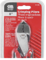
My recommendation is to look at the original type connectors, and bring it back to the ways of the Yamaha. Get rid of those wire nuts, and put it back to what normal should or could be. after the 12 bucks for the diode, and if you can't borrow a real crimper, another 10 bucks at menards for a GB style crimper, that self sealing silicon, get three rolls to cover up what you just uncovered. It it awesome. Use the heat shrink over the splice points. I used a regular bic lighter for the heat shrink.
self sealing tape, available at all the normal hardware stores
http://www.amazon.com/Gardner-HTP-1010-Purpose-Silicone-Self-sealing/dp/B00004WLKT
my photo album
My recommendation is to look at the original type connectors, and bring it back to the ways of the Yamaha. Get rid of those wire nuts, and put it back to what normal should or could be. after the 12 bucks for the diode, and if you can't borrow a real crimper, another 10 bucks at menards for a GB style crimper, that self sealing silicon, get three rolls to cover up what you just uncovered. It it awesome. Use the heat shrink over the splice points. I used a regular bic lighter for the heat shrink.
self sealing tape, available at all the normal hardware stores
http://www.amazon.com/Gardner-HTP-1010-Purpose-Silicone-Self-sealing/dp/B00004WLKT
Attachments
DARKMIDKNIGHTWARRIOR
XS400 Addict
Ok first, I could not find anything on the specs of the diode and yes it is one-way. Either the one from my link or Arf's link from Boats.net will be about the same cost. The other pic he posted is the best of a stock unit I have seen. Yes you could possibly use one from Radio Shack if you knew the specs on it. When I looked the other day one guy said 1 amp was good another said it was too much and another said it was not enough. On the stuck connector I was thinking it sound like it melted together before I even read your last post. If you could let us know exactly what color wires are in it please. I don't think it is the flasher relay plug from the pics. If Xschris could read any info off the diodes on his harness maybe the Radio shack would work. I think that as long as that ground wire is solid and a clean frame ground it will work. The best way to clean up that wiring would be heat shrink and solder. I think if you get the diode and both the relays replaced and clean up those wires you could be off and running. Again I will help any way I can.
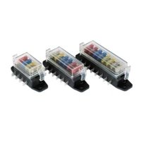
Thanks for the replys yes I, was looking at getting the diode from RS if they have it.Mean while today I`ll probaly remove the yellow connectors and rewire them up.Im waiting on some cash to be able to get the relays.There was a member that said he was going to give some to me but that has fallen through since i havent heard back from him in a week or s ne other thing I want to do is clean up and organise my fuses they are just a glob of wires and sticking up so I need to find one of those boxes I have some members use to make them all nice and neat.
Another issue I need to address is my turn signals,they work on the left side but not on the right.When the left signals are flashing I can here the relay clicking.when I turn on the right side blinkers nothing but a dead zone.no clicking in the relay.I`ll probaly dig into the tail light and check the wiring in there also.
Do any of you guys that have bought those boxes for organising the blade fuses know where I can buy them?
Also what is the cost there abouts?
ne other thing I want to do is clean up and organise my fuses they are just a glob of wires and sticking up so I need to find one of those boxes I have some members use to make them all nice and neat.Another issue I need to address is my turn signals,they work on the left side but not on the right.When the left signals are flashing I can here the relay clicking.when I turn on the right side blinkers nothing but a dead zone.no clicking in the relay.I`ll probaly dig into the tail light and check the wiring in there also.
Do any of you guys that have bought those boxes for organising the blade fuses know where I can buy them?
Also what is the cost there abouts?
Last edited:

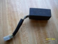
Ok today after fixing the crappy wiring job going to my rectifier that had the yellow twist on connectors I found a hidden surprise underneith the bracket where the rear part of the tank bolts on.If you remember a couple of paragraphs back I posted a white plug that I could get apart.Well today I got it apart.This component was attached to it.What is it?Its got 6 wires and a number 21N
Attachments
Last edited:
Looks like the turn signal auto cancel.
my photo album, shows my fuse block, how I made mine, costs, and where I bought my parts.
Northern Tool 12 bucks, only difference I needed to add a voltage reg, you probably don't.
http://www.xs400.com/media/albums/342/
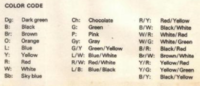
I put the pic with the color codes, so you can validate it against the wire diagram.
here is the color code too.
my photo album, shows my fuse block, how I made mine, costs, and where I bought my parts.
Northern Tool 12 bucks, only difference I needed to add a voltage reg, you probably don't.
http://www.xs400.com/media/albums/342/
I put the pic with the color codes, so you can validate it against the wire diagram.
here is the color code too.
Attachments
Such a big box for a turn signal counceler.So just to confirm if I leave it unplugged its not go to interfere with any other poart of the elctrical systems?